Ok i've been fiddling with amplifiers for about 3 years now, just replacing various components which are clearly blown (normally black or the like.) I know the names of the components, it's just sometimes i feel unsure of what they do.
I mean you see capacitors everywhere and zener diodes. But why them?
My main question is:
Can you tell me what these few things do?
All ref. this pic:
http://ampguts.realmofexcursion.com/Powerbass_XA-3000D/inside2.jpg
1. The first (from the left) set of 12 fets (6 either side of the board), bound with 6 clamps to the sink.
Also the further right on either side of these is the same and have 3 legs but 2 of the legs are soldered together? Why is this?
2. What is purpose of the 8 caps around the fan. They are stabilising the voltage i assume? Part of a smoothing/rectification ciruit?
3. The board that sticks up by the 3 toroids?
I think it has a name? smcc board? Something like that.
I know it's a lot of questions. But if someone could please give me a run down of the various parts of the board and what they do i would greatly appreciate it!
I'll ask about the output side in a minute.
If anyone has any links or anything of the basics of class D design, please would you send me them.
Thank you.
Hi
This is car amp so:
1.Those are output mosfets.
Those that have 2 pins together are diods, rectifiers... makes DC from AC...
2. To make DC you need rectified AC, and capacitor(s) make it solid DC.
3. I'm not really sure what you mean, but those toroids are output inductors of this amp. board is called PCB, if you wanted to know that, not sure..
And BTW, this is output side...
Hmmmmmm.
So what are these 20 fets???
http://ampguts.realmofexcursion.com/Powerbass_XA-3000D/inside3.jpg
either side of the board. I thought they were output fets?
Also on the near side of the amp here, there are 4 random fets what are they?
http://ampguts.realmofexcursion.com/Powerbass_XA-3000D/inside1.jpg
Yes it is a car amplifier.
I'm confused now, cheers for the help")
So what are these 20 fets???
http://ampguts.realmofexcursion.com/Powerbass_XA-3000D/inside3.jpg
either side of the board. I thought they were output fets?
Also on the near side of the amp here, there are 4 random fets what are they?
http://ampguts.realmofexcursion.com/Powerbass_XA-3000D/inside1.jpg
Yes it is a car amplifier.
I'm confused now, cheers for the help
How many would you like to have?
Some amps draw 300A easy, some even put out more then 100A ac, on coz of this you need lots of fets to share current
what are you confused about?
Some amps draw 300A easy, some even put out more then 100A ac, on coz of this you need lots of fets to share current
Where? can you show on picture?Also on the near side of the amp here, there are 4 random fets what are they?
what are you confused about?
Well you know, 3000w amp, if this is true output, and can hold overall eff. of say 85% and pretty low voltage, say 12v for this amp, it would have to be 300A..
Those are probably rectifiers, I guess this amp has them on only one side, it could have them on both
yea 20 for input, probably 5 for every primary and it has 8? output fets [you dont need so many of them, coz current is lower, but voltage is much higher then on input]
Those are probably rectifiers, I guess this amp has them on only one side, it could have them on both
yea 20 for input, probably 5 for every primary and it has 8? output fets [you dont need so many of them, coz current is lower, but voltage is much higher then on input]
I see, so the probable reason for the input fets blowing is too low a voltage.
Thus to still produce the same power they draw a lot more current.
Makes sense, thanks.
Also i found this, as i get about 110v across the 8 fets (output) and 14v ish across the inputs.
What do the 2 toriods do then between the set of 20 fets (input side)
http://ampguts.realmofexcursion.com/Powerbass_XA-3000D/inside1.jpg
The caps by them, on this amplifier i a struggling to repair, are buzzing quite agressively. Wheras others of this model which work fine i have pulled apart do not make any noise other than the fan spinning and a tiny high pitched noise.
Low input voltage is bad yes, they can fail too if output goes..
Those are two main transformers, making 14v to 110v. This is core of supply/amp
Sounds like caps could be dead, did you check if they are getting how? also did you check if there is pure DC on them?
Also what is amp current draw it on state?
Those are two main transformers, making 14v to 110v. This is core of supply/amp
Sounds like caps could be dead, did you check if they are getting how? also did you check if there is pure DC on them?
Also what is amp current draw it on state?
Amp current draw is minimal, i have blown my dmm so i cannot test the draw bit i can tell you it's tiny as it's running off a 4a battery charger which is paralleled to a pair of 3ah batteries.
I have tried it connected to a load and got no change in the condition of the amplifier. No power lights just fan spinning and caps buzzing.
I'll test the caps later. I just have to remove the entire board again.
So those caps will be part of a rectifier? Why would i need another low voltage other than the 12/14v side?
On my output side (specifically by the rca input connections and the gain crossover knobs) i also noticed that a resistor was getting very hot, i have no idea what it does, but it's not directly connected to the battery (+ve or -ve). I checked this using the conductivity setting on my multimeter.
amp will probably be ok without heatsink for test..
Do you know how amps work? I mean yea, you can't not have capacitors, and to say, they are part of power supply as are rectifiers [diodes]
what other low voltage? You have 12v input, and signal for amp to work, thats it
Do you have DC on your output? BRW, output is not connected to input
Do you know how amps work? I mean yea, you can't not have capacitors, and to say, they are part of power supply as are rectifiers [diodes]
what other low voltage? You have 12v input, and signal for amp to work, thats it
Do you have DC on your output? BRW, output is not connected to input
Right, but the capacitors are not rated as high as the ones around the fan. I assumed that the ones around the fan were the ones for the high voltage (output) side.
I don't have voltage on the output termianls, no. Neither DC nor AC. Even if i connect a load to the terminals.
However i do get the 110v ish across all the output fets.
I don't have voltage on the output termianls, no. Neither DC nor AC. Even if i connect a load to the terminals.
However i do get the 110v ish across all the output fets.
The big ones are supply caps, highest rated in amp [compared to their C size] Other 2 on other side of fan are most likely part of out LC filter along with those red ones. If they are not, those red ones with those resistors could form RC filter
Does your amp even starts up? does supply start to work? maybe there is a problem even on remote, thing that turns amp on. You will have to check every part of amp, is this and that working, doing so you will find where normal status stops to be.
But as I read, you said you get 110v on output fets, so supply should be working ok, so now question is, does amp section work too? I do hope you have scope, this would be really easy to check
I do have a scope (got myself one a few months ago). It all seems well,
Except the power LED is not illuminating. When i put a load across the speaker termianls and power it on, nothing happens.
I hear a relay click in after about 2 seconds of power on. (output protect relay?) The fan spools up immediatly after applying voltage to the remote.
I have connected an input (RCA's and played a tone through them) but where should i be able to find these outputs? As i seem to only be able to pick up this AC across the rca termianls themselves.
I assume the 'amp section' is the 20 fet part? Low voltage high current side?
Ok maybe led is dead, amps seems to be working as far as to Damp, did you check if there is signal on output[small sine, high freq.] or befor output inductor?
2s for relay to click, seems ok, output is connecter to output terminals [check if this is true]
And fan is also working
So one of two thing I can think of:
1. input is not conecter anymore or dead, so signal doesn't pass
2. amp section is not working
car amp is made of supply[20fets] and amplifier[8fets], so we have seen that suppy is working, but not amp section, so check this, then, if there is signal, put sine signal on input and check how far it goes, does it even enters amp.
Ok, i will when i'm home from work.
The LED itself is ok, i passed a small voltage through it and it illuminated.
So check the ouput on the relay is connected to the output terminals.
When you say input is dead, i have that one hot running resistor (this is from the rca/ gains section to the fets/ toriods). I will replace that when i can.
What makes the power LED illuminate? Is it a feedback sort of thing from the amplication section.
As i just thought that would turn on when voltage is in the power section.
Thankyou very much for your help. I have learned a lot already!
Wait a minute, RCA are not connected to any fet by only resistor/s
Mark them on some picture, I must see which ones you are talking about. Maybe it is on if they heat up, but only if the are the right ones. I am thinking you don't think the right ones, since RCAs have small voltage, olmost no current, so based on that, nothing can heat up..
Mark them on some picture, I must see which ones you are talking about. Maybe it is on if they heat up, but only if the are the right ones. I am thinking you don't think the right ones, since RCAs have small voltage, olmost no current, so based on that, nothing can heat up..
Exactly but that is what is concerning me. I mean these resistors are GLOWING they are really that hot.
I'm stuggling to find a picture.
I know RCA's should have little voltage and current. I don't know if these resistors are directly connected to the inputs but they look like they are.
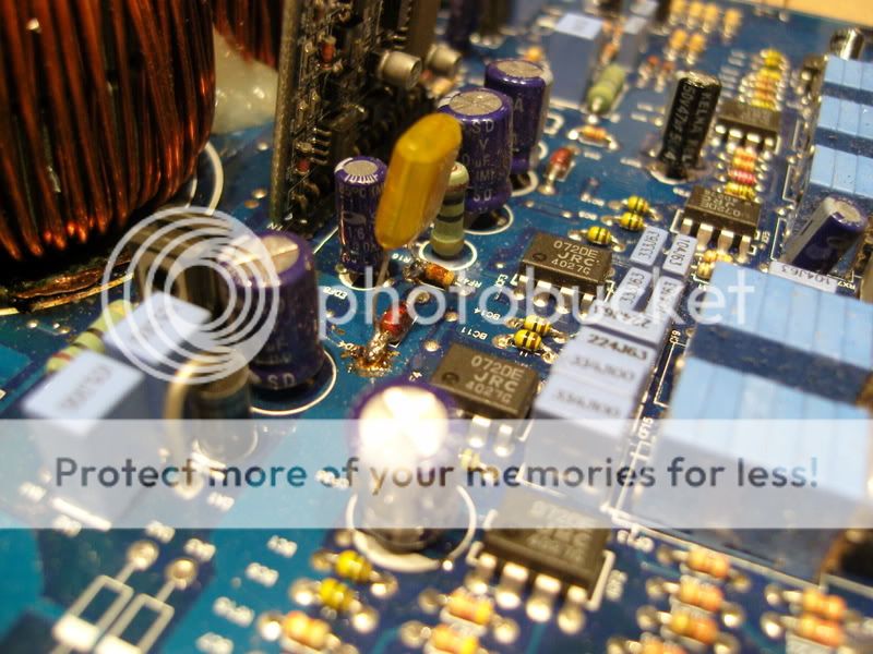
The green resistor standing up by that board i was talking about. There is a resistor either side of the pair of capacitors.
It's red hot once the relay clicks in.
I'm stuggling to find a picture.
I know RCA's should have little voltage and current. I don't know if these resistors are directly connected to the inputs but they look like they are.
The green resistor standing up by that board i was talking about. There is a resistor either side of the pair of capacitors.
It's red hot once the relay clicks in.
After relay, ee? Ok you need to find out what are they for, maybe to generate voltage for IC? coz it looks to me there is diode, that would make nice voltage regulator for ICs, and I am thinking on, if IC are dead, there could be short, and full voltage on those resistors, making them way too hot
It also looks like amp was repared before, no?
It also looks like amp was repared before, no?
- Status
- This old topic is closed. If you want to reopen this topic, contact a moderator using the "Report Post" button.
- Home
- Amplifiers
- Class D
- What does this do?