Is there a particular heat-sink that anyone can recommend ?
ZALMAN CNPS10X FLEX Socket LGA1366, LGA1156, 478, LGA775, AM3, AM2+, AM2, 754, 939, 940 compatible High Performance CPU Heatsink - Ebuyer

What you're looking at is a 700g beast capable of dissipating 100W when fanned.
The amp produces like, 5-10W?
Hi V-bro Yes i recall a mention if the fan somewhere in the posts. One thing I found from working with lots of gainclones, the more refined the design/results get the more annoying the little issue become.
I am planning to still run the fan on low volts but off a separate battery, this isn't an issue as I have to run 4 fans plus i can use that battery for solenoid switchings and other little non audio path matters.
In the past I have found with gainclones very carefully worked out shielding of components helps, I suspect it may be even more of an issue with D amps, I know that I found moving my hands around the amp board and other hooked in circuits and wiring without anything playing one can hear variations in residual noise levels with the gain turned up.
My feeling with amps is that the final sound is as much about minimising a whole raft of really small issues as much as it is about the type of amp or chip used etc.
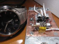
For example the by far the best sounding gainclones I have built are very small with ultra short circuit paths, meticulous star pointing and shielding, the choice of actual parts was far less important in the end than the construction method. A pic is attached of the micro clone built around an LM1875 chip runs on 12 or 24V dual rail and has 3200uf caps just off the board not shown the whole thing fits in a copper coffin just a little bigger than the circuit itself. It runs dead cool even on 24v despite running a gain of only 16. These modules are actually my benchmark, up until this 2050 amp nothing has come close for detail, resolution and soundstage, they basically sound like really nice tube amps but it is all changing now!
There are probably a myriad of small issues with these boards and I am still trying to come to grips with them but I learn every day.
I am planning to still run the fan on low volts but off a separate battery, this isn't an issue as I have to run 4 fans plus i can use that battery for solenoid switchings and other little non audio path matters.
In the past I have found with gainclones very carefully worked out shielding of components helps, I suspect it may be even more of an issue with D amps, I know that I found moving my hands around the amp board and other hooked in circuits and wiring without anything playing one can hear variations in residual noise levels with the gain turned up.
My feeling with amps is that the final sound is as much about minimising a whole raft of really small issues as much as it is about the type of amp or chip used etc.
For example the by far the best sounding gainclones I have built are very small with ultra short circuit paths, meticulous star pointing and shielding, the choice of actual parts was far less important in the end than the construction method. A pic is attached of the micro clone built around an LM1875 chip runs on 12 or 24V dual rail and has 3200uf caps just off the board not shown the whole thing fits in a copper coffin just a little bigger than the circuit itself. It runs dead cool even on 24v despite running a gain of only 16. These modules are actually my benchmark, up until this 2050 amp nothing has come close for detail, resolution and soundstage, they basically sound like really nice tube amps but it is all changing now!
There are probably a myriad of small issues with these boards and I am still trying to come to grips with them but I learn every day.
Last edited:
Is there a particular heat-sink that anyone can recommend ?
ZALMAN CNPS10X FLEX Socket LGA1366, LGA1156, 478, LGA775, AM3, AM2+, AM2, 754, 939, 940 compatible High Performance CPU Heatsink - Ebuyer
It is quite surprising that it needs so much heatsinking.
I wouldn't be surprised if the operating temperature can be dramatically lowered with better output filter inductors. I do know for a fact from tests I have done that other inductors have a dramatical effect on the idle current consumption. Put the two together and we may have something?I have ran all my AMP4 and AMP11 modules from 41hz during power up tests for a few minutes with no heatsinking at all! This is at 24Vdc, 8 ohm dummyload...
A larger heatsink would be no problem if only the power stage was placed on the bottom of the PCB, now you have to find something that fits in between all the higher profile components...
I know some other modules with this very same problem...
An externally hosted image should be here but it was not working when we last tested it.
Different coils make chips cooler?
How does changing the coils make the output chips run cooler and reduce current consumption at idle?
I wouldn't be surprised if the operating temperature can be dramatically lowered with better output filter inductors. I do know for a fact from tests I have done that other inductors have a dramatical effect on the idle current consumption. Put the two together and we may have something?
How does changing the coils make the output chips run cooler and reduce current consumption at idle?
Hey V bro.. now this inductor thing is interesting, on a mildy related issue I found that the sound of the amp was substantially different when I changed the speaker cables out from straight figure 8 thin cable to cat 5 twisted cables (3 cat 5 cables per length). I noticed the resolution was better by a fair margin and the chip seems to run pretty much without any heat at all, certainly I can't feel any heat at the heatsink.
It had some heat with the small figure 8s and I thought the change was just due to burn in but maybe not.
No other amp I have ever used has seemed quite so responsive to a cable change of this type. mmmmm, got me thinking now.
I also wonder how the heat varies with speaker impedance?
I imagine a hot amp is not a happy amp!
Burned up
Many of the early fanless amps burned up due to the small heatsink and thick glue that mounted them on the first version boards. That's why Sure went to the fan. I wouldn't run without a heat sink.
I imagine a hot amp is not a happy amp!
Many of the early fanless amps burned up due to the small heatsink and thick glue that mounted them on the first version boards. That's why Sure went to the fan. I wouldn't run without a heat sink.
Hey V bro.. now this inductor thing is interesting, on a mildy related issue I found that the sound of the amp was substantially different when I changed the speaker cables out from straight figure 8 thin cable to cat 5 twisted cables (3 cat 5 cables per length). I noticed the resolution was better by a fair margin and the chip seems to run pretty much without any heat at all, certainly I can't feel any heat at the heatsink.
It had some heat with the small figure 8s and I thought the change was just due to burn in but maybe not.
No other amp I have ever used has seemed quite so responsive to a cable change of this type. mmmmm, got me thinking now.
I also wonder how the heat varies with speaker impedance?
I imagine a hot amp is not a happy amp!
I find the Sure responsive to all the system changes I've tried. I think of it this way: The Sure has so little coloration of its own to mask the sound of the other components. This makes changes to the other components more audible.
This makes the Sure an ideal test amp for designing speakers, comparing DACs, interconnects, power supplies, sources, etc.
Of course there are other superb amps out there, but it is hard to find one as clean as the Sure with as much power for less than $100, including power supply and mods.
-dr_vega
Holy cow, mounted on with glue! No wonder they cooked, a perfect insulator I imagine.
Sendler I think it may have been you, correct me if I am wrong but somewhere I read about changing the caps on the 5v regulator and it turned out that tant caps worked better? I am going to cut the wires to the fan tomorrow and will make a few mods in that area while at it, power supply routing etc, if it was you are you still running those caps?
Sendler I think it may have been you, correct me if I am wrong but somewhere I read about changing the caps on the 5v regulator and it turned out that tant caps worked better? I am going to cut the wires to the fan tomorrow and will make a few mods in that area while at it, power supply routing etc, if it was you are you still running those caps?
Holy cow, mounted on with glue! No wonder they cooked, a perfect insulator I imagine.
Sendler I think it may have been you, correct me if I am wrong but somewhere I read about changing the caps on the 5v regulator and it turned out that tant caps worked better? I am going to cut the wires to the fan tomorrow and will make a few mods in that area while at it, power supply routing etc, if it was you are you still running those caps?
It is thermal conductive glue. Without a fan, my heat sink got quite warm to the touch. That would indicate the heat was making it from the chip to the heat sink ok. The heat sink just isn't large enough to dissipate the heat at higher volume levels. A larger heat sink or a fan solved the heat problem for us.
I think you guys are aiming higher than I am, which is great. For my purposes, improved input caps and output coils along with a bit more tank capacitance next to the chips gives me a performance level that is very satisfying. And the tiny fans I added give me reliability without any audible degradation (at least not audible to me).
Now I using the Sures as the test amps to work on improving my speakers and preamps.
-dr_vega
I am looking to get the best possible results from the amps as I have come about this from the reverse direction, I have spent almost 3 years developing the speakers, pre amp and front end of the system. The whole system is off the grid, including the TT and amplification is the weak point. The gainclones are very very good, the problem is power supplies, once your off the grid this becomes problematic due to the dual rails, in practice it is hard to keep the rails utterly equal and you need a lot of batteries and chargers. If the voltage varies between rails the distortion goes up.
Needing only one rail per amp makes it much easier and if the amps can sound better still then why not.
Of course going battery power is a bit of pain but once you have everything off the grid you realise just how much better things can be, put just one component back on the grid and the magic is contaminated.
I require pretty much the same as you, utterly clean non coloured amplification and I feel these modules pretty much meet the criteria but as said I am looking for that last bit of magic constantly, but I certainly think I am very close.
I actually wonder if perhaps we should start an ultimate 2050 tuning thread where we can distill things into a easier to digest format, it sure take a long time to go through the whole 115 pages to find the pearls enclosed in the thread.
I wouldn't give the Sure that much credit, what you experience is always the good chipset. Making changes to a load changes almost any amplifier's performance, that's got nothing to do with inherntly low colouration. Class T is inherently sensitive to the load and the output filter should be tailored to the load quite well to keep it linear in the audio band. This is one slight down side to these amps.
Yes the inductors change the current draw and usually low current draw is a good sign I would think. I only have real life experience and just some unproven ideas about what is the reason. The first time I saw this phenomenon I was quite surprised too, I saw the idle current drop 35% on an amplifier just by changing the inductors!!
The fact many people overlook who are familiar with conventional amplifiers is that a class D amplifier ALWAYS switches. Due to this the temperature the switching devices are showing is not so much related to the load and in-band output level. Actually with class T the swithing frequency is also variable and lowest at idle and I have tested amps that ran cooler at max output than at idle! It's pretty much reverse psychology...
So, this switching wave form is always there, even when it is all silent in the room, the output filter is permanently filtering this energy, that's how it happens.
Oscon
I haven't done any tweaks to the power supply other than providing the fan with it's own 5v regulator but will soon try adding some OsCons to the supply pins of the TC2000 and maybe add some larger caps to the 32v.Holy cow, mounted on with glue! No wonder they cooked, a perfect insulator I imagine.
Sendler I think it may have been you, correct me if I am wrong but somewhere I read about changing the caps on the 5v regulator and it turned out that tant caps worked better? I am going to cut the wires to the fan tomorrow and will make a few mods in that area while at it, power supply routing etc, if it was you are you still running those caps?
Current draw with air cores
I will measure the current draw of the one amp I have that still has the air toroids on it to see if it is different from the Wurth XXL coils that I now use.
I wouldn't give the Sure that much credit, what you experience is always the good chipset. Making changes to a load changes almost any amplifier's performance, that's got nothing to do with inherntly low colouration. Class T is inherently sensitive to the load and the output filter should be tailored to the load quite well to keep it linear in the audio band. This is one slight down side to these amps.
Yes the inductors change the current draw and usually low current draw is a good sign I would think. I only have real life experience and just some unproven ideas about what is the reason. The first time I saw this phenomenon I was quite surprised too, I saw the idle current drop 35% on an amplifier just by changing the inductors!!
The fact many people overlook who are familiar with conventional amplifiers is that a class D amplifier ALWAYS switches. Due to this the temperature the switching devices are showing is not so much related to the load and in-band output level. Actually with class T the swithing frequency is also variable and lowest at idle and I have tested amps that ran cooler at max output than at idle! It's pretty much reverse psychology...
So, this switching wave form is always there, even when it is all silent in the room, the output filter is permanently filtering this energy, that's how it happens.
I will measure the current draw of the one amp I have that still has the air toroids on it to see if it is different from the Wurth XXL coils that I now use.
I will measure the current draw of the one amp I have that still has the air toroids on it to see if it is different from the Wurth XXL coils that I now use.
That I would be very interested in!
I haven't done any tweaks to the power supply other than providing the fan with it's own 5v regulator but will soon try adding some OsCons to the supply pins of the TC2000 and maybe add some larger caps to the 32v.
There was a posting in this thread where someone (I forget who) referenced a paper that said (if I remember correctly) that putting a very fast cap after a voltage regulator could destabilize the VR. VRs need a relativly high ESR.
I left my 5V VR and cap alone. But I do plan to put a faster tank cap on the back of the board at the TC2000 5V power leg.
-dr_vega
disagree
I saw that. I disagree totally. I've seen many tests of caps for digital supply and a stack of electrolytic/ Oscon/ ceramic always measures the quietest and stiffest. Oscon and chip cap must be placed within millimeters of the device and have a good ground.
There was a posting in this thread where someone (I forget who) referenced a paper that said (if I remember correctly) that putting a very fast cap after a voltage regulator could destabilize the VR. VRs need a relativly high ESR.
I left my 5V VR and cap alone. But I do plan to put a faster tank cap on the back of the board at the TC2000 5V power leg.
-dr_vega
I saw that. I disagree totally. I've seen many tests of caps for digital supply and a stack of electrolytic/ Oscon/ ceramic always measures the quietest and stiffest. Oscon and chip cap must be placed within millimeters of the device and have a good ground.
I wouldn't give the Sure that much credit, what you experience is always the good chipset. Making changes to a load changes almost any amplifier's performance, that's got nothing to do with inherntly low colouration. Class T is inherently sensitive to the load and the output filter should be tailored to the load quite well to keep it linear in the audio band. This is one slight down side to these amps.
*clip*
I agree that Tripath is the real magic. And I think the TK2050 chipset are the best of the Tripath. I use "Sure" as a shortcut for "Tripath TK2050 with two TP2050 power chips."
But I think the Sure board is pretty well laid out as well, which makes it a hell of a bargain.
I think Class D amps are less affected by load changes than analog amps, since the transistors are just used as switches. The output filter, of course, varies with load, but if you design for 3 ohms or so, it should be good for anything you hook up to the amp.
-dr_vega
Hi all, I just run my fan from a separate l7805 reg, works fine and lowers the noise floor...
I'm guessing a good tank cap has low ESR? So far I've only upgraded input cap and inductors, and I am tempted to give a tank cap upgrade a go...
I figure less when 1000uF would be best when using a SMPS which is switching at 60KHz?
Hi, any reason for going for Panasonic FM caps in particular or were the just what you had in the box?I added a 680 uF Panasonic FM tank cap to each channel on the back of the board. It helps with the large, effortless feel of the sound.
I'm guessing a good tank cap has low ESR? So far I've only upgraded input cap and inductors, and I am tempted to give a tank cap upgrade a go...I figure less when 1000uF would be best when using a SMPS which is switching at 60KHz?
Last edited:
- Status
- This old topic is closed. If you want to reopen this topic, contact a moderator using the "Report Post" button.
- Home
- Amplifiers
- Class D
- Sure Electronics New Tripath Board tc2000+tp2050