Hi all i have a 41hz amp 6b i think its great but need a bit more power. I have seen the sure 2x100 watt and wondered how thay sound against the 41hz amps
I have the 2x50 watt version of the sure, but hav not had time to play with it. I have on the other hand made a 41hz amp10b, several amp9(b) and many amp32s.
I have played with the sure ta2024 amp which should sound comparable to the amp32 according to specs, but the lower quality of the components is easily heard on the sure. It has some background hiss which improved when I changed the bulk caps to u-low ESR types, but there is still som hiss in the background. I also did the other mods and removed the resistor network, changed the input caps etc. which improved the sure amp much. In my oppinion the amp32 is still better, among others it has better 3d feeling and a totally dark background (even compared to my mid end Class A/B receiver).
If you're up for it you could consider the amp10b or the amp9b which are not that hard to solder, but then you miss out on the fun of modding
") . Just be careful as you easily spend more than the 41hz cost on upgrades.
. Just be careful as you easily spend more than the 41hz cost on upgrades.my take:
I.
- Input caps
- tank caps (and thus depending on your PSU also a soft start)
II.
- Input and feedback resistors
III.
- output filter incl. toroids
- voltage regulator
- re-route power rails on PCB and remove diodes (amp likes every bit of voltage)
IV. Might not be worth doing
- re-wiring pins 24 on both TP2050s to 21,22 (Vdd) instead of gnd
- exchange C22&27 for 470pF as per the TC2000 data sheet
I think I may have damaged the inductor solder pads when I replaced them w/ 10uh toroids
. Can I move them to the + and _ outputs instead/connect them to the speaker wire?I think I may have damaged the inductor solder pads when I replaced them w/ 10uh toroids
duuh, no?
If you number the pads from 1 to 8, pads 1, 4, 5 and 8 lead to the chips. There is no alternative to those pads. The traces are quite broad so you could scratch some of the black coating and solder to the traces.
The pads 2, 3, 6 and 7 pass by the common mode and differential mode capacitors and lead to the speaker terminals. You can connect there, but the longer your leads are the more you will radiate RF.
smallest coil?
Is it possible to get a decent filter with a smaller coil and doubling the caps? Or does this still have the pronounced over shoot? I would think that the best sounding coil would be the smallest coil.
.
Is it possible to get a decent filter with a smaller coil and doubling the caps? Or does this still have the pronounced over shoot? I would think that the best sounding coil would be the smallest coil.
.
I did get a hold of the printouts of the Bode plots from the filter simulation so I can post them here. I don't have access atm to the machine where I installed pspice to do the simulations. I'm using the student's version I picked up to download from somewhere in the web. It is simple enough to try for yourself. Cost me an hour or so to do the simulations I wanted. There are also turorials out there. If you have the patience I can run your simulation in a few days, swkbkk.
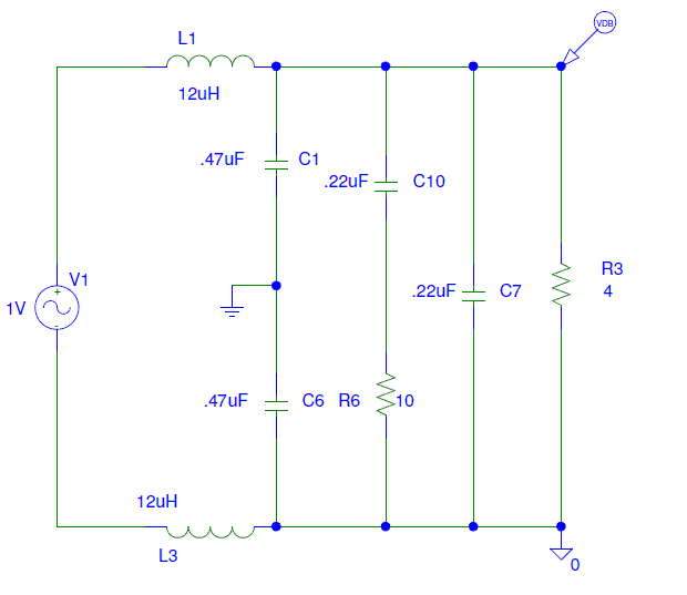
Attached is the schematic of the output filter I built.
C1 and C6 are the common mode capacitors, C_C,
C10 is the Zobel capacitor C_Z and
C7 is the differential mode capacitor, C_D,
R3 is the load where I used 4 Ohms throughout
Each bode plot has a header containing a filename that contains the values of the parts "left to right".
The first one is the one in the schematic, the second is what tripath recommends in the data sheet text, the third is what the sure board has fit and the last is the filter as posted by swkbkk.
Is it possible to get a decent filter with a smaller coil and doubling the caps? Or does this still have the pronounced over shoot? I would think that the best sounding coil would be the smallest coil.
.
you can try no coil, but I fear this will end you in jail for interference with cops' and air traffic radio
Plus it might heat your speakers.
Single driver can run with no filter
A single driver speaker can get away with no output filter for low power and dedicated, short (no) speaker wires but the rest of us are stuck with a coil.
http://focus.ti.com/lit/an/sloa023/sloa023.pdf
The best coil to have in series with your tweeter would be no coil, the second best would be air core but we can't have that either without coming up with a good shielding scheme. So, we have to use metal core coils where I'm thinking that the smaller the value the better the sonics. Let the shunt caps do the work. This is more load for the amp but we have plenty of power to work with.
you can try no coil, but I fear this will end you in jail for interference with cops' and air traffic radio
Plus it might heat your speakers.
A single driver speaker can get away with no output filter for low power and dedicated, short (no) speaker wires but the rest of us are stuck with a coil.
http://focus.ti.com/lit/an/sloa023/sloa023.pdf
The best coil to have in series with your tweeter would be no coil, the second best would be air core but we can't have that either without coming up with a good shielding scheme. So, we have to use metal core coils where I'm thinking that the smaller the value the better the sonics. Let the shunt caps do the work. This is more load for the amp but we have plenty of power to work with.
never mind the shielded speaker cables - nice article!
Hot air
Remove the plastic fan. Use some hot air from a blow dryer or a heat gun carefully on the heatsink. The glue looks more like a silicone rubber than an epoxy so it does eventually respond to some heat. Pry up on the heatsink with a moderate amount of pressure, well before the point of breaking or digging into anything and start working some heat on and off of the heatsink to slowly start bringing up the temp until the glue finally softens and it comes off.how the heck do you take off the fan/heatsink?
Remove the plastic fan. Use some hot air from a blow dryer or a heat gun carefully on the heatsink. The glue looks more like a silicone rubber than an epoxy so it does eventually respond to some heat. Pry up on the heatsink with a moderate amount of pressure, well before the point of breaking or digging into anything and start working some heat on and off of the heatsink to slowly start bringing up the temp until the glue finally softens and it comes off.
thanks guys, i'll give it a go.
C1+C6=C10=C7 a rule?
I have been doing some sims with pspice student and it is easy to learn. The 12uH coils are already about as small as you can go and are actually a little low for 8 ohm speakers even when they are good into 4 ohms. I see that most of the proposed filters use cap values where C1+C6=C10=C7. Is there some theory why this is better to have the combined values all the same or can C1=C6=C10=C7 measure just as well? I also see the advantage of the zobel. If the speaker goes open at full power it prevents each cap circuit from basically shorting at it's resonant frequency of approximately 35k.I installed pspice to do the simulations. I'm using the student's version I picked up to download from somewhere in the web.
Attached is the schematic of the output filter I built.
C1 and C6 are the common mode capacitors, C_C,
C10 is the Zobel capacitor C_Z and
C7 is the differential mode capacitor, C_D,
R3 is the load where I used 4 Ohms throughout
Follow the circuit
Can you follow the circuit to the next component that the trace was going to and connect on right there?
Crap. I tore one of the R13 feedback resistor pads
Can you follow the circuit to the next component that the trace was going to and connect on right there?
Because I ruined one board already I was wondering when the next one comes in ... I was planning to only replace the input capacitor with Mundorf Mcap 2,2uF and further leave the board as it is.
Can I connect a Panasonic FC 1500uF 50V directly to the VCC (+) and GND (-) connection ? Or maybe 2 in parrallel?
Can I connect a Panasonic FC 1500uF 50V directly to the VCC (+) and GND (-) connection ? Or maybe 2 in parrallel?
Can I connect a Panasonic FC 1500uF 50V directly to the VCC (+) and GND (-) connection ? Or maybe 2 in parrallel?
I think so as long as you watch out the polarity.
I did connect two Rubycons (1000uF, 50V) in parallel directly to VCC and GND. On mine, they are in addition to the ELNA SILMIC IIs that I used to replace the original caps. I just put the *extra* Rubycons because I bought them before I found the ELNAs.
You can find some pictures of what I have done in the post #519 on page 52.
Surface mount resistors sound better
Surface mount resistors sound better than through hole. I don't know what brand of resistors those are on the Sure but the Susume surface mount resistors I use in my new design stepped attenuators sound better than the Yageo through hole type I was using, which kill the ever popular Dale resistors. I wouldn't bother with any of the resistors on the 2X100. The input cap and the output filter are the big roadblocks in this amp.Because I ruined one board already I was wondering when the next one comes in ... I was planning to only replace the input capacitor with Mundorf Mcap 2,2uF and further leave the board as it is.
Surface mount resistors sound better than through hole. I don't know what brand of resistors those are on the Sure but the Susume surface mount resistors I use in my new design stepped attenuators sound better than the Yageo through hole type I was using, which kill the ever popular Dale resistors. I wouldn't bother with any of the resistors on the 2X100. The input cap and the output filter are the big roadblocks in this amp.
Those SMD resistors might sound better than those through-hole resistors, but your categorical claim about SMD resistors sounding better than through-hole resistors is dubious. There are a lot of circuit- and system-dependent particulars you're glossing over, and a whole bunch of resistors you haven't heard in that circuit . . .
Feel free to correct me if you have heard all resistor combinations.
Replace away
Sorry. Replace away.
.
Sorry. Replace away.
.
Those SMD resistors might sound better than those through-hole resistors, but your categorical claim about SMD resistors sounding better than through-hole resistors is dubious. There are a lot of circuit- and system-dependent particulars you're glossing over, and a whole bunch of resistors you haven't heard in that circuit . . .
Feel free to correct me if you have heard all resistor combinations.
- Status
- This old topic is closed. If you want to reopen this topic, contact a moderator using the "Report Post" button.
- Home
- Amplifiers
- Class D
- Sure Electronics New Tripath Board tc2000+tp2050