riktw said:@audio1st
can you tell me why you modded it and what the mods are supposted to do?
becouse i can just mod it like you did but i want to know what the mods are supposted to do.
like, why did you remove the diodes, and does replacing C1 and C2 with 1 cap affect the input filter and how much?
and why did you reroutet the power supply, is the circuit boards routing bad?
The mods you refer to are just the final touches, if you are still trying different power supplies, then I don't recommend you remove the diodes or re route the power..
C1 and C2, also C5 are in parallel with the new power supply caps which are now low ESR, so they are replaced with better quality.
I didn't think the PS routing was perfect as it was.
Note, C1 and C2 are not input filter caps, the input filter caps are C16,C17 and C24,C25. This is the most important mod. Remove the 4 caps and replace C16 and C24 with something like THIS
whelibob said:
yes im using only one 12v 9Ah battery. i havent connected the 5volt mute. my speakers impedance is 8ohm. and there shouldn't be any shortciruiting in my wiring. my guess is that its just a manufacturing fault since in the beginning when it worked only the other channel was giving out sound and just after 5minutes of listening it also muted.
Has the battery voltage dropped? needs recharging?
nope battery is just recharged and tested also with 24V with two batteries in parallel. most likely going to send it back, if and when sure electronics replies to my email.audio1st said:
Has the battery voltage dropped? needs recharging?
audio1st said:
The mods you refer to are just the final touches, if you are still trying different power supplies, then I don't recommend you remove the diodes or re route the power..
C1 and C2, also C5 are in parallel with the new power supply caps which are now low ESR, so they are replaced with better quality.
I didn't think the PS routing was perfect as it was.
Note, C1 and C2 are not input filter caps, the input filter caps are C16,C17 and C24,C25. This is the most important mod. Remove the 4 caps and replace C16 and C24 with something like THIS
Audio1st,
can you pls elaborate on the rerouting of the power rails?
I can follow the idea of shorting the diodes and doubling the rail. But what is the notion behind the cuts and bridge around the LM317?
Also you seem to have taken out almost any ol' cap on the board.
Putting some low ESR around the rail like C7-9 and C11-13 seems like a good idea to me, too. Do you find it necessary to actually eliminate the original caps on these spaces? I figure even if there are lower ESRs around the original caps shouldn't hurt or can they?
Also C1&2 seem non-suspect to me, what was your reason for getting at them?
Lastly, you replaced some caps in the output stage, but not all of them. Is there something we can learn from this?
thx
I haven't gone back and taken the time to read the posts since I last posted but I would
like to revise my original statement on this amp...
I originally said that I didn't care for the highs, but I started out with the amp mounted directly on top of the switching power supply. Once I went back and cased the 2050 amp in a separate box the hardness in the upper mids and treble left, for the most part. I have tried it now with three different speakers; DCM TimeFrame TF600's, Infinity Reference Series Kappa 6's and a pair of DIY Usher 2-ways I constructed from a design by Dennis Murphy. It really excels in the mids with lushness like a cross between good class A solid state gear and vacuum tube equipment. This may be common to all good class D gear but I have only owned the Sonic Impact amp so can't comment with any real authority. It also has excellent bass but might exhibit slightly less control with the Kappa 6's than my Behringer A500, which is about twice the power.
Anyway, for the money it is ridiculously good!
ElFishi said:
Audio1st,
can you pls elaborate on the rerouting of the power rails?
I can follow the idea of shorting the diodes and doubling the rail. But what is the notion behind the cuts and bridge around the LM317?
Also C1&2 seem non-suspect to me, what was your reason for getting at them?
thx
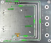
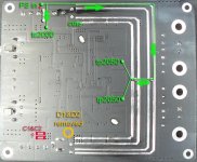
Hi ElFishi,
As I said the mods are just what I have done for my own use and are not necessarily a recommendation..
I am very happy with my boards and have just shared some ideas.
Here is a picture of the original PS route.
Attachments
ElFishi said:
Lastly, you replaced some caps in the output stage, but not all of them. Is there something we can learn from this?
thx
I did actually replace them all.. except the Zobel.
Attachments
audio1st said:
I did actually replace them all.. except the Zobel.
You have zobel caps on your board (C34, C48) and resistors? My sure board didn't have zobel components on board, thats why it was a bit rough on highs. After adding zobel filter the sound was much nicer, also change these grey caps(output capacitors) with something better.
Regards Ales
I think that all these boards from sure are without zobel network.
Audio1st,
of course I am aware that these are your choices and thanks for sharing them.
All I'm trying is to pick your brain, so I can make my choices in a more educated manner.
I still can't follow your cut of the little streak leading up to C5 (I guess). Isn't that unconnected now?
Also, am I wrong or did you replace the output inductors, too? They look different and yet so similar.
After reading Ales' remark I checked with my board to find that indeed C34,48 and R38-41,45-48 are missing.
If you look at the picture from sure-electronics as attached to the first post of this thread you could get the feeling that these components are missing there, too.
ElFishi said:
After reading Ales' remark I checked with my board to find that indeed C34,48 and R38-41,45-48 are missing.
If you look at the picture from sure-electronics as attached to the first post of this thread you could get the feeling that these components are missing there, too.
SURE do some strange things, who knows why they decided to leave them off?
I hadn't removed my heatsink, it is very well attached to the chip and didn't fancy the chip coming off with the heatsink.
I may now try a Zobel across the speaker terminals and thanks to Ales for spotting the missing parts.
The cut to C5 was easier for me than removing C5. I added a 100nF Wima across C3 to replace it, just my preference..
I have 2 boards so that is why the inductors look different.
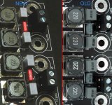
Another thing that bothers me is that bypass caps have value 6.8uF(caps in read rectangle) instead of 100nF also I think that big mistake is that the config pin(24 on TP2050) is connected to the ground instead of connecting it to the vdd pins(21,22 on TP2050). Now these two pins are connected on the 5V line via 10k resistor. I increased value to the 47k but nothing significant happened, I was hopping that I will reduce heat but without any luck.
Regards Ales
Regards Ales
Attachments
mravlcax said:I think that big mistake is that the config pin(24 on TP2050) is connected to the ground instead of connecting it to the vdd pins(21,22 on TP2050).
Regards Ales
I re-wired pins 24 on both TP2050s to 21,22.
I could not notice a remarkable drop in temperature.
But then I don't have a thermometer. I just touch the heatsink with my hand and it feels moderately hot, just as before.
ElFishi said:
I re-wired pins 24 on both TP2050s to 21,22.
I could not notice a remarkable drop in temperature.
But then I don't have a thermometer. I just touch the heatsink with my hand and it feels moderately hot, just as before.
Thank you for doing this instead of me
") . So the only option is just bigger heatsink.
. So the only option is just bigger heatsink. Regards Ales
Hi
I have the DIYPARADISE Charlize amp - TA2020, and I want a bit more power.
I was thinking of buying one of the Audiocostuire amps using the Tripath TAA4100A:
http://www.autocostruire.com/catalog/product_info.php?cPath=42&products_id=330
This Sure Electronics board is so much cheaper. How would these compare?
Measurements
My amp arrived yesterday, and I did some measurements to make sure it was working correctly:
-Channel imbalance (L to R): within .04dB
-DC Offset Ch1:-21mv, Ch2: -5mv
-Power output at 1KHz at clipping: 20W into 8 ohms, 31W into 4 ohms
-Frequency response (both channels were nearly identical):
1K 0 dB
500Hz: 0dB
100hz: -.02
50hz: -.13
20Hz: -.70
----
2K: +.01
5K: +.08
10K: +.32
20K: +1.07
Note that the zobel parts were missing from my PCB also. When I added them, the respose at 20KHz improved by a bit to +.93dB relative to 1kHz.
I'll repeat these measurements after I mod the unit, but don't expect any measurable change.
Mike
Re: Measurements
Can you please tell us what psu voltage did you use when you were measuring this and what values does your components have in zobel filter. I have 470nF and 10ohm.
Regards Aleš
mikebarney said:My amp arrived yesterday, and I did some measurements to make sure it was working correctly:
-Channel imbalance (L to R): within .04dB
-DC Offset Ch1:-21mv, Ch2: -5mv
-Power output at 1KHz at clipping: 20W into 8 ohms, 31W into 4 ohms
-Frequency response (both channels were nearly identical):
1K 0 dB
500Hz: 0dB
100hz: -.02
50hz: -.13
20Hz: -.70
----
2K: +.01
5K: +.08
10K: +.32
20K: +1.07
Note that the zobel parts were missing from my PCB also. When I added them, the respose at 20KHz improved by a bit to +.93dB relative to 1kHz.
I'll repeat these measurements after I mod the unit, but don't expect any measurable change.
Mike
Can you please tell us what psu voltage did you use when you were measuring this and what values does your components have in zobel filter. I have 470nF and 10ohm.
Regards Aleš
- Status
- This old topic is closed. If you want to reopen this topic, contact a moderator using the "Report Post" button.
- Home
- Amplifiers
- Class D
- Sure Electronics New Tripath Board tc2000+tp2050