Thanks guys.
Im novice just trying to learn a bit from this excellent forum.
Yes i did try stopping fun but there is no difference.
I just got the board and using 12v power supply from my tripath.Still looking for power supply.
And also with modes ,i have that updated version so called.
Should i do some changes ?.
There were lots of photos at the beginning of the forum but most of it don't work anymore.
thanks
Take a look at this Power supply from Modders (aka Sure Electronics I'll wager), appears to be a Meanwell clone that puts out from 26 to 32v dc, for US $38.49 shipped. The Sure board and the power supply when shipped, are both tracked from the Sure website, and the value was marked low enough to get through customs with no duty.
New 27V DC 13A 350W Regulated Switching Power Supply - eBay (item 110487975668 end time Mar-30-10 23:49:09 PDT)
Hi barbieboy..
So what power supply you using at the moment?
Hi, I went for the Meanwell 24v as recommended by the good folks here. It has a pot on the rear to rev it up to 27v which is what I am doing.
32v
I use 36v Meanwells at 32v.i found it didnt sound any good cranked above 25v? is this just me?- i seam to loose the midrange quality. (24v mean well smps)
Dr Vega,
Would you mind posting a picture of your air-core inductors with paper and tin foil shields? In fact any pics of your amp would be cool. Also, bypassing the PIOs with the Daytons means you are running them in parallel?
Regards,
Free
Yes, bypassing caps means running in parallel. I'll try to get some pictures, I tried a while back and couldn't get anything worthwhile, but I have a new camera now.
I've stopped using the tinfoil shields. They smoothed out the sound too much. I don't know why, but they have a significant affect on the sound. I need to try adding a ground wire to them.
-dr_vega
i found it didnt sound any good cranked above 25v? is this just me?- i seam to loose the midrange quality. (24v mean well smps)
Interesting, will give that a try once I have the coils done, thanks for pointing this out. But am I right in thinking that the amperage goes down when increasing the voltage ? What volume were you pupping out ?
this was at all volumes, but more noticable at under 90db peak (A weighted) (prob in part as my speakers increase in distortion above this)
when runing my setup at over 25v on the meanwell 24v, it just sounded how i would have previously expected class d to sound- a little harsh all round.
i have no idea why realy, maby its running components above there ideal voltage inside the smps, maby the chip prefers lower voltage, maby its the reduced ampage available, maby its just mine!!
the only thing im sure of is it isnt psychoacoustic, i went back to checking this and having 5 or 6 pairs of speakers handy inc quad esl's im in a lucky position to test on different loads.
blind tests were easy, even my wife nailed it 1st time, and she frankly could care less!......(untill it sounds bad, then she complains!
the room is accoustically treated, so no bass boom room nodes etc to give the differences away.
when runing my setup at over 25v on the meanwell 24v, it just sounded how i would have previously expected class d to sound- a little harsh all round.
What power rating is this supply? When it is 'on the edge' it is possible the higher voltage is pushing the supply too far and causes the voltage to drop under load (soggy supply voltage, makes class T amps sound really bad...)
You could monitor the supply voltage under load with a scope. When you see the voltage 'dance with the music' then obviously your supply isn't holding up...
I had a similiar issue with a 24 volt 600ma wall-wart that produced distortion at higher volumes, possibly the result of "soggy supply voltage" as V-bro describes. I am now using a 27v (27to32v range) 13amp Meanwell clone running at 30 volts with no distortion. I understand that the Tripath chip requires a certain voltage range for optimum preformance, but can someone explain what effect a higher current can have on sound quality?when runing my setup at over 25v on the meanwell 24v, it just sounded how i would have previously expected class d to sound- a little harsh all round.
Dr Vega,
Would you mind posting a picture of your air-core inductors with paper and tin foil shields? In fact any pics of your amp would be cool. Also, bypassing the PIOs with the Daytons means you are running them in parallel?
Regards,
Free
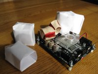
Well let's see if this works. This is the first time I've tried to upload pictures. One picture is the front of the board with the air-cores (held together with masking tape) and the tinfoil/paper condoms. There are no input caps installed in that picture. You can also see my cute little frameless fan glued right to the stock heatsink.
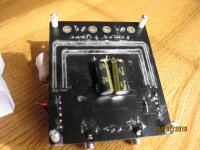
The back of the board shows the Panasonic FM 680uF tank caps and the fattened negative return trace below them to the left.
-dr_vega
Attachments
The back of the board shows the Panasonic FM 680uF tank caps and the fattened negative return trace below them to the left.
-dr_vega
That should be "return trace below them to the right."
-dr_vega
I understand that the Tripath chip requires a certain voltage range for optimum preformance, but can someone explain what effect a higher current can have on sound quality?
Would you be able to do a speed running record on a muddy track?
Would you be able to do a speed running record on a muddy track?
Thanks V-bro, I wouldn't be able to do a speed running record on any track but I understand the analogy.
The fan of my Sure tk2050 causes some interference on my amplifier. I can hear the rpm of the fan through the speakers connected. If I stop the fan the interference is gone. Do I need the fan, I'm running the amp with 18,5V voltage and using only one channel. I think I'm using 1x40W power max.
Thanks!
Thanks!
Did you dummyload the other channel? These amps don't really like being run "open loop"...
Also, I said it before, fans output EMI, often a substantial amount and I would do anything to remove it. It would be the first thing I would mod. It should also not be necessary to have it, all TK2050 amps I have built (up to 50Vdc!) don't need employment of a fan at all.
Either that heatsink is too small or the output filter is not working properly....or both....(probably both...)
- Status
- This old topic is closed. If you want to reopen this topic, contact a moderator using the "Report Post" button.
- Home
- Amplifiers
- Class D
- Sure Electronics New Tripath Board tc2000+tp2050