Actual values of Output coil and cap
Has anyone actually tested the coils that are labeled "220" to confirm that they are, in fact, 22uH?
Likewise has anyone confirmed that the output caps are .47uF? It's hard to read the label on my caps but it kind of looks like "68."
-dr_vega
Has anyone actually tested the coils that are labeled "220" to confirm that they are, in fact, 22uH?
Likewise has anyone confirmed that the output caps are .47uF? It's hard to read the label on my caps but it kind of looks like "68."
-dr_vega
Re: Actual values of Output coil and cap
mine are easy to read: 684j100
output cap reads 224j100
dr_vega said:Has anyone actually tested the coils that are labeled "220" to confirm that they are, in fact, 22uH?
Likewise has anyone confirmed that the output caps are .47uF? It's hard to read the label on my caps but it kind of looks like "68."
-dr_vega
mine are easy to read: 684j100
output cap reads 224j100
Re: Re: Actual values of Output coil and cap
Thanks, El. If the output coil is 22uH and the output cap is .68uF, then the filter corner is about 41kHz.
I think I'm going to change mine to 10uH and .33uF. That'll give me 87.6kHz which is what the 15uH/.22uF combination that Tripath recommends produces. I happen to have some 10uH coils on hand, which is why I'll be using them instead of 15uH.
BTW, after about 10 hours of use, the highs have come in a little. They're still rolled off some, but not nearly as much as they were.
-dr_vega
ElFishi said:
mine are easy to read: 684j100
output cap reads 224j100
Thanks, El. If the output coil is 22uH and the output cap is .68uF, then the filter corner is about 41kHz.
I think I'm going to change mine to 10uH and .33uF. That'll give me 87.6kHz which is what the 15uH/.22uF combination that Tripath recommends produces. I happen to have some 10uH coils on hand, which is why I'll be using them instead of 15uH.
BTW, after about 10 hours of use, the highs have come in a little. They're still rolled off some, but not nearly as much as they were.
-dr_vega
I'm about to re-do the output stage as well. I am going to follow the design mentioned in the text of the tripath datasheet (not the schematic)
"The TK2050 works well with a 2nd order, 80kHz LC filter with LO = 10uH and CO = 0.47uF and RZ = 10 Ohm/1W and CZ = 0.47uF."
I got myself some iron powder toroidal cores and enameled wire. Now I need to do some knitting...
"The TK2050 works well with a 2nd order, 80kHz LC filter with LO = 10uH and CO = 0.47uF and RZ = 10 Ohm/1W and CZ = 0.47uF."
I got myself some iron powder toroidal cores and enameled wire. Now I need to do some knitting...
One more mod
While browsing the Tripath docs, I came across the section on Modulator Feedback. One resistor, Rfbc, needs to be matched to the supply voltage "for best signal-to-noise ratio and lowest distortion."
On the Sure 2*100watt board these are resistors R13, R17, R25, and R31 (one for each output from the TC2000 chip).
The board comes with 15kOhm resistors, which are correct for a 32v supply. Applying Tripath's formula gives these values for other popular voltages:
24v = 11k
26v = 12k
28v = 13k
30v = 14k
32v = 15k
34v = 16k
36v = 17k
Since the audio signal passes through these resistors, you might want to replace them with some nice metal films, like the Holcos that PartsConnexion has on sale cheap right now.
While you're upgrading resistors in the signal path to metal films, you also might want to upgrade the input resistors (R11 and R32). Keep their values at 22kOhm.
If you run with any of your gain switches "On," upgrade R18, R19, R20, and R21, too, keeping their 22kOhm values.
I have not yet done any of these updates, but I've ordered the Holcos. I don't expect them to make a lot of audible difference, but who knows, right?
-dr_vega
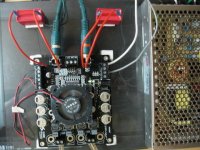
I am happy to report that I finally collected the courage and have replaced the input caps following the excellent instructions from Audio1st, Whelibob and others here. Thank you all!
I tried to follow the path taken by Whelibob as it seems to require minimum "desoldering and soldering" except that I had to use some extension wires as my WIMA MKP10s are bigger.
I removed C16, C24 and removed C17 and C25. Then I soldered the wires from the WIMAs to where C16 and C24 used to be. I hope I have done it right. Do I also need to remove the registers R14 and R34?
I get popping sound when I turn the board; not too loud but still audible. Is it normal or have I done something wrong?
I just used the wires I salvaged from an old computer PSU cables. Are they ok for connecting the capacitors? Or Is there any special kind of wire that I should have used?
Attachments
swkbkk said:Do I also need to remove the registers R14 and R34?
I get popping sound when I turn the board; not too loud but still audible. Is it normal or have I done something wrong?
I just used the wires I salvaged from an old computer PSU cables. Are they ok for connecting the capacitors? Or Is there any special kind of wire that I should have used?
Good looking work, swkbkk! The wire looks fine. If you get any noise on the line, you can twist together each pair of wires. Not necessary, but it will help in an electrically noisy environment.
I generally use Cat5 or Cat6 wire because it is easy to get, easy to work with, solid core (so it stays where you bend it), and it is a very good quality conductor. Plenum rated Cat5/6 has teflon insulation, which is very nice.
I don't know what resistors R14 and R34 do. They aren't on the Tripath reference schematic. I left mine in place.
The popping sound is from the capacitors charging. It is normal. If you add more power supply caps, it will get louder. You can do muting circuits, either with the mute control or with relays on the speaker outputs, to keep the speakers off until the caps are charged, but that's a bigger project.
Just one suggestion, if you're running at high volume, you might want to replace your power supply wire with heavier gauge.
Good work.
-dr_vega
Thank you, dr_vega for the compliment and suggestions. After having braved on my first diy project, albeit being a rather small mod, I feel a little more confident now 
I just used "Sure" supplied 16AWG wires that came with the board. I will replace them if I can find thicker wires somewhere.
I think I will try to enjoy the music for a while before my next mod. Actually, I am waiting for the results on your and ElFishi's mod on the output stage. I hope you experts can come up with some good mods on the output stage that I can copy and emulate.
This board is really amazing. Thank you all again for being helpful and patient to newbies like me.
Cheers!
swkbkk said:I just used "Sure" supplied 16AWG wires that came with the board. I will replace them if I can find thicker wires somewhere.
Actually, I am waiting for the results on your and ElFishi's mod on the output stage. I hope you experts can come up with some good mods on the output stage that I can copy and emulate.
This board is really amazing. Thank you all again for being helpful and patient to newbies like me.
Cheers!
I hope you're hearing improvements from your cap swap. It feels so good when you make an amp sound better and you know you did it yourself! I'm not putting down those who send their amps off to others to do the upgrading, but I find it very rewarding to know I made it happen with my own hands, especially when things go wrong and I have to scramble to fix my mistakes and make things right.
16AWG should be plenty. It looks smaller to me in the picture. Of course, some people think more is always better, so if you come across some 0000 welding cable, it'll make great power lines
I've replaced my output coils with 10uH coils I bought from board member Arjen Holder. He makes them for his MkIII TA2020 boards. They're very nice toroids rated at 3 amps and wound on the MicroMetal type 2 cores that Tripath recommends. They're small enough to fit on the TK2050 board and they're inexpensive:
http://cgi.ebay.com/Choke-coil-for-...ash=item3ca3e1bae8&_trksid=p4634.c0.m14.l1262
I upgraded the input caps at the same time I installed the coils, so I don't know for sure what part of the improvement was the caps and what was the coils. But the total improvement is significant, much more open, detailed, and balanced. The mids are slightly too forward, but my highs are finally present.
The parts are still burning in and I haven't changed the output caps or added a Zobel or changed the input and feedback resistors yet, so I expect things to get better still. But I love what I'm hearing so far.
I'm also waiting for a fan to arrive so I can play it louder!
-dr_vega
Hi guys
need a little help around here,
followed the Audio1st great instructions for changing the
input caps,
i used WIMA MKP10 2.2uF and alps 50k pot,
removed & bridged c24&c16
removed c17&c25
removed the bj 6ca's also
with the advice from dr_vega i left the r34&r14 intact
connect it all ,and nothing..no sound just some white noise that was not there before...
so i removed the r34&14 also,and the sound is back,
but for some reason i can only hear high freq,NO BASS AT ALL,
the high's are great,but no mid nor bass...
can someone please light my way ?
thank you all for shearing ,i could never done that without you
coz i don't really know electricity,and all i have is your pictures and my good hands,
thanks
Hi,
I have received my board and it already sounds pretty darn good. I'm ready to do the mods as Audio1st has posted here.
I have a RadioShack 50k pot. For the cap I couldn't find a WIMA, but found this at partsexpress, will that work also?
http://www.parts-express.com/pe/showdetl.cfm?Partnumber=027-415
Thanks everyone for putting the time into documenting these mods.
@2noisy
If you place the Caps before the board and bridge originals, you must remove R14 & R34. If you simply replace the onboard caps then the resistors may stay.
Are you sure you have 2.2uF caps? I can think of no other reason for lack of bass?
@nrg2009
Those caps look ideal..
If you place the Caps before the board and bridge originals, you must remove R14 & R34. If you simply replace the onboard caps then the resistors may stay.
Are you sure you have 2.2uF caps? I can think of no other reason for lack of bass?
@nrg2009
Those caps look ideal..
nrg2009 said:Hi,
I have received my board and it already sounds pretty darn good. I'm ready to do the mods as Audio1st has posted here.
I have a RadioShack 50k pot. For the cap I couldn't find a WIMA, but found this at partsexpress, will that work also?
http://www.parts-express.com/pe/showdetl.cfm?Partnumber=027-415
Thanks everyone for putting the time into documenting these mods.
I use those Dayton caps and like them a lot. I think they are good or better than any other Polypro film caps at any price (ymmv). They are a bit big, but can work either before the input or on short jumpers like swkbkk did.
On this project I'm using the Dayton Polypro foil caps which are even better but only go up to .47uF. I'm crossing over to a subwoofer at 100Hz, so I don't need the extra low end, but if you do, you can bundle five .47uFs in parallel. A big bundle, but still cost-effective for 1st rate sound.
-dr_vega
audio1st said:@2noisy
If you place the Caps before the board and bridge originals, you must remove R14 & R34. If you simply replace the onboard caps then the resistors may stay.
Are you sure you have 2.2uF caps? I can think of no other reason for lack of bass?
well ,i just found out that i can only hear the high's ,
because i burn my mid range speaker( KEF cersta10 )
happened when i forgot to connect the 10000uF 50V cap...

while connecting it to another set of speakers it's all good.
i finely replaced the caps on boarb just like "SWKBKK" did
and removed the R14&R34 before that..
do i need to put something instead or it's ok?
Thank you for your help
Hope i made everyone laugh a bit
Output stage mod
As I understand from various posts here, main things that concern the change to the output stage seems to be:
1. Inductor Coils
2. Output Capacitors
3. (missing) zobel capacitors and resistors
Is there some kind of formula that determines what the output inductor and output capacitor values should be?
The sure board, if I understand correctly, use 22uH inductor and 0.68uF capacitors while the schematics suggest 10uH and 0.47uF. I wonder how these values affect the sound quality. I will definitely wait for some experienced opinions from other experts like Audio1st, dr_vega, ElFishi before attempting any mod on the output stage, but my curious mind just keeps wondering what these things do to the sound quality.
Another thing I noticed while trying to "study" the manuals is that something called "HBR"s in the Tripath manual and C29, C32, C37, C41 are having different values; 0.1uF in the Tripath and 6.8uF in the Sure manual. Can this be also related to the choice of the output caps and inductor coils?
The cutoff frequency of an LC-low pass filter is
1/(2 \pi \sqrt(LC))
The TP2050 datasheet says
"The TP2050 works well with a 2nd order, 80kHz LC filter with LO = 10uH and CO =0.47uF".
That's what I am going to try (haven't started yet), even if it gives a cutoff of 73KHz.
The schematic in the same datasheet lists 15uH and .22uF resulting in 88kHz cutoff. Higher, but maybe not decisive.
The sure board otoh is stocked with 22uH and .68uF yielding a cutoff at 41kHz. Given that the attenuation of the LC filter is sloping and starts well before the cutoff the fear is that the filter transmission could affect audible highs.
I am not really worried about the values of the HBR-capacitors. They are for filtering the supply rails. I think they shouldn't be too small, but I can't see that they are too big.
Another thing I noted, however, with the sure board is that they ignored the recommendation to offset the values of the feedback capacitors (c19,21,22,27) for each channel. I exchanged C22&27 for 470pF as per the TC2000 data sheet. I can't hear a difference, but I feel better now...
ElFishi said:
Another thing I noted, however, with the sure board is that they ignored the recommendation to offset the values of the feedback capacitors (c19,21,22,27) for each channel. I exchanged C22&27 for 470pF as per the TC2000 data sheet. I can't hear a difference, but I feel better now...
Hi ElFishi,
I thought this may have been the cause of the heat, I take it that it made no difference?
Thanks for your trouble..
PS, would changing the 680nF output caps to 220nF caps work?
Thank you, ElFishi for your detailed explanations and opinions. I am really loooking forward to hearing the result on your mod on the output stage. Please keep us updated on your progress as time permits if possible.
I am a bit relieved to hear that you aren't too concerned by the high value of the HBR capacitors used in the board. I did a bit of digging around on the Internet to learn a little more about "High frequency bypass capacitors" and I was getting the impression that higher frequencies require lower valued capacitors and the 6.8uF stated in the Sure schematic seemed a little too big compared to 0.1uF stated in the Tripath schematic. But then I have no idea what exactly is considered to be high and low in this application
And thank you for sharing your experience on trying different values on the feedback capacitors. I also noticed that in the tripath manual and was getting concerned about "in-band audio noise" whatever it may be. As you notice not much difference, I won't probably go through the trouble of removing the heat sink and replacing those small SMD capacitors. I am not still confident with my soldering skills yet
This I'm sure is a very silly question to the veterans, but since I'm a noob I'll ask it anyway.
I look at the schematic on page 10 of the manual (page 13 of 15 in Adobe) and it seems to me that R14 and R34 (22k) are not in the signal path, but connected to ground? So my question is that if that is true why remove them? are they some sort of snubber?
Thanks
I look at the schematic on page 10 of the manual (page 13 of 15 in Adobe) and it seems to me that R14 and R34 (22k) are not in the signal path, but connected to ground? So my question is that if that is true why remove them? are they some sort of snubber?
Thanks
- Status
- This old topic is closed. If you want to reopen this topic, contact a moderator using the "Report Post" button.
- Home
- Amplifiers
- Class D
- Sure Electronics New Tripath Board tc2000+tp2050