-Thanks, but could you recommend an amp like that that is about 100 watts per channel or more(is better) and with 2 channels. It doesnt have to be the bare amplifier it could be assembled. And my limit of $300.
-Thanks
Sorry, I'm going the other direction. I'm currently working on a 3-watt per channel tube amp.
-dr_vega
A simple solution for On-Off thumping
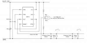
I found a simple solution to eliminate on-off thumping noise based on the information provided in this web page 555 and 556 Timer Circuits (Schmitt trigger). It requires just a single 555 IC, a capacitor, a resistor, two SPST relays (or a single DPST relay) and a protection diode. Optional LED indications can be included very simply as shown in the attached diagram. I am not an electronics engineer and I don't know how to draw "standard" circuit diagrams. So I just tried to show how I lay the things on my strip board. I hope you can understand it.
Note that 555 accepts anything between 4.5VDC and 15VDC according to the website above. The coil voltage of the relays must be selected to match the input voltage you are supplying accordingly. I read that most relays can tolerate a bit higher voltage than specified. Personally, I have used two 5V SPST (Normally Open) relays with contact rating of 10A@30V. I supply 5.7 VDC from a phone charger which I savaged from my old Nokia phone.
The turn-on delay time is a function (a multiplication for approximation) of the capacitor and the resistor values but I suggest using a low capacitance and a high resistance (rather than high capacitance and a low resistance) so that we get "instant off" effect. If the capacitor is large, it will take time to de-activate the relay and it might cause turn-off noise. Personally, I have used used 100uF and 50K preset turned down to around 30K to give me about 3 seconds turn-on delay and almost instant turn-off. It's also important that the power source does not have big capacitors of its own. The nokia phone charger I am using doesn't seem to have any (or very little) capacitor in it, which is good thing for "instant off" effect.
The 4 pin RGB LED connected as in the diagram lights Red when the amp is turned on and after the delayed time, will also light Blue when the relays are activated and the speakers are connected illuminating some purplish colour.
I have built the simple circuit and tested and it works for my setup. Please note that it's NOT a speaker protection module, but just a simple solution to eliminate thumping noise during on and off.
Attachments
Hi all, just a quick question, i have modded my Teac A-H300 reference amp and added a set of pre-outs, can i drive this amp board via those as a power amp?
if so would it just be a case of plugging the RCA's in, the speakers and the DC power plug? would i still need to add a pot to adjust the gain or is the gain set to max out the door?
Thanks for any help,
Adam.
if so would it just be a case of plugging the RCA's in, the speakers and the DC power plug? would i still need to add a pot to adjust the gain or is the gain set to max out the door?
Thanks for any help,
Adam.
Hello all,
I have a similar questions also. Has anyone sucessfully used a preamp with this board, or only used the sure rotary encoder, or a pot ? I have a decent class A preamp that I'd like to use, but the documentation seems to warn against using any preamp, even though there are high and low gain adjustments on the board. Also I have a spare chipamp PSU that puts out ~ +/-30 vdc. Can this be used if I only use the +30v and the ground to power the board ?
Thanks,
PJN
Getting rid of the pop...
YouTube - Tripath anti pop turn on/off circuit for SLEEP and MUTE
It can be very simple...
Here's what I designed:

It's the sequence that matters, first transistor can toggle the sleep and mute in one draw and the second a speaker relay...
YouTube - Tripath anti pop turn on/off circuit for SLEEP and MUTE
It can be very simple...
Here's what I designed:
It's the sequence that matters, first transistor can toggle the sleep and mute in one draw and the second a speaker relay...
Thanks for your suggestion.
Not sure if I understood your design right. Means that I find sleep and mute connection on the sure board ?
Is the 12 Volts a separate supply or just the power input of the board ? Usually it should be then at least 24 Volts if your design is integrated into the powersupply connection of the board.
Not sure if I understood your design right. Means that I find sleep and mute connection on the sure board ?
Is the 12 Volts a separate supply or just the power input of the board ? Usually it should be then at least 24 Volts if your design is integrated into the powersupply connection of the board.
Do you have a breadboard? I suggest you buy one and make the circuit and experiment with it....
It can run on any voltage between say 10 and 100V as long as you tweak the capacitor and resistor values correctly.
For the sure board you can take a 24V speaker relay and get some caps that are rated at least 25V.
It's not rocket science, just a cheap and simple, yet very functional circuit. Basically the transistors make ground in a 1-2, 2-1 sequence. You can choose several things to make ground (relays, chip function pins etc). For instance the sleep and mute function on the Tripath chips are activated that way. But it would suffice to just ground the mute with T1 and then it would be most effective to have T2 do a speaker relay.
You can even connect Hmute to T2 with a similar resistor value towards the base to ensure quick speaker disconnecting when something goes wrong....
Last edited:
Yes, similar to yours on your video. But it is still brand new in package since purchase months ago ...Do you have a breadboard?

So this is one opportunity to use the breadboard. Of course I would test the result with cheaper speakers. I know that the sure board is a bit tricky ...
And thanks much for your help.
v-bro,
Asking you as 41hz expert
What would be an analog for the current Sure's 2*100 from 41hz? (not in terms of SQ but IC's used)
Leaning towards Sure, but incase...
Well the Sure probably sounds pretty good for the money, but if you also value good efficiency the 41hz equivalent (AMP4, AMP11) is definitely better. It definitely runs cooler, I always test them at moderate level with no heatsink at all and at 30Vdc. This is definitely not recommended with a Sure board!! Something has got to be badly oscillating there...
Yes, similar to yours on your video. But it is still brand new in package since purchase months ago ...
So this is one opportunity to use the breadboard. Of course I would test the result with cheaper speakers. I know that the sure board is a bit tricky ...
And thanks much for your help.
Shame!
Always do test with cheapo speakers until the amp is completed, in a box, thoroughly tested and shiny as can be!
Has anyone seen the new Sure amps. I was looking into the new 2X300 watt one. Anyone know the True RMS rating per channel @ 4 ohms?
-Thanks
Yes, especially the fan on it looks really promising.
And I have heard several TAS series amplifiers in commercial amps, they never really managed to thrill me...
- Status
- This old topic is closed. If you want to reopen this topic, contact a moderator using the "Report Post" button.
- Home
- Amplifiers
- Class D
- Sure Electronics New Tripath Board tc2000+tp2050