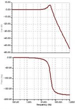
Ok. THX for your efforts. I didn't really expect simulations 
This means I could expect problems in the highs if i run 16R load on a 4R optimised filter. Probably sounding too sharp.
Now - a bit off topic but helps me to bring it all together I guess:
Another problem is probably the driver impedance/linearity and its filter-interaction.
The digital-amp THD-N increases pretty strong on impedance increase of the load.
Which is normal if you don't have a driver linearization ( zobel filter) applied. Correct?
Without driver linearization I can expect increase of distortion on higher frequencies.
This would add an extra degradation. My highs would be even more messed up. Correct?
Would it be good to add a zobel-filter to the driver to get the impedance linear first?
In the end there is probably no way around to simulate the whole outputstage-zobelfilter-driver to get a proper result. Anybody around who has done this?
However. I can't really complain a lot about my current soundquality (outputfilter set to 8R on 16R speakers) according to datasheet. But if I can get it better. I'll try. You tell me!
THX a lot for your support.
Ouroboros said:Anyone looking for an off-the-shelf shielded inductor could look at the new SER2918H range from Coilcraft. This is surface-mountable and uses copper strip as the winding material.
Coilcraft (in the UK at least) will supply small quantities to hobbyists. Pricing is shown for most parts on their website.
Hi! I'm a student and new to class d amps.
I was looking for an suitable inductor for my design (Based on the new IRAUDAMP7d from IRF).
The SER2918H looks nice, but can it handle the high supply voltage of +56/-56V (total of 112V)?
Tnx in advance!
The voltage issue is in two parts. First of all is the insulation between the winding and the core. The second is the voltage difference between each turn of the winding.
The 22uH parts in this range only have 7 turns, so the turn-to turn potential difference can be quite high.
Looking at the samples I have, the insulation on the wires appears to be a thick polyurethane coating, so it should be adequate at the voltages you mention. There's no other insulation layer on these parts though (The copper strip forming the coil is 'free-wound' (not on a bobbin), so it might be wise to contact the manufacturer to see what operating voltage they rate them at.
I think even the thinnest insulation is enough for this low voltage. But I can't believe that core loss could be that low as they calculate on the site. I think they will produce significant heat in wire because of flux leakage near the airgap. Not much, but significant.
By calculating (extrapolating) from ESR curves, Q at 400 kHz seems to be around 50, (max. 100) so 1 W (min. 0.5 W) loss is exepted.
By calculating (extrapolating) from ESR curves, Q at 400 kHz seems to be around 50, (max. 100) so 1 W (min. 0.5 W) loss is exepted.
This is a very good tool for calculating filter values:
http://www.ti.com/tool/LCFILTER-CALC-TOOL
http://www.ti.com/tool/LCFILTER-CALC-TOOL
- Status
- This old topic is closed. If you want to reopen this topic, contact a moderator using the "Report Post" button.
