Hope you all had a very good Christmas 
Been thinking a bit duing the hollydays") ... I have now tryed some different designs using self oscillation, both UcD and pre-filter designs.
... I have now tryed some different designs using self oscillation, both UcD and pre-filter designs.
I think it has been bificult to make work and I have all the time had some problems with beeting when using more than one amp. I know that it is some what a matter of proper PCB layout and taming good care of EMI, but it is still an inherent problem with selfoscillating designs.
Now I think I'll try some clocked designas using a good x-tal clock to syncronice the amps.
Then I'm wondering whether the self oscillating designs in theory should have better distortion performance???
Any thoughts??
I actually cant see why that should be. It of cource is a matter of feedback around the output stage in the clocked design, which is inherent in the self osc. designs.
Another thought is about the output filter. If good coils (right ferite material) and good caps are used I can't see these contribute much to the distortion. In a clocked design, I don't think it is likely to get as much feedback from after the filter, and therefore it will probably not be possible to reduce the effect as much as with a self osc. design.
Maybe I'm all wrong here, so please comment with your knowledge.
Best Christmas regards Baldin
Been thinking a bit duing the hollydays
... I have now tryed some different designs using self oscillation, both UcD and pre-filter designs.I think it has been bificult to make work and I have all the time had some problems with beeting when using more than one amp. I know that it is some what a matter of proper PCB layout and taming good care of EMI, but it is still an inherent problem with selfoscillating designs.
Now I think I'll try some clocked designas using a good x-tal clock to syncronice the amps.
Then I'm wondering whether the self oscillating designs in theory should have better distortion performance???
Any thoughts??
I actually cant see why that should be. It of cource is a matter of feedback around the output stage in the clocked design, which is inherent in the self osc. designs.
Another thought is about the output filter. If good coils (right ferite material) and good caps are used I can't see these contribute much to the distortion. In a clocked design, I don't think it is likely to get as much feedback from after the filter, and therefore it will probably not be possible to reduce the effect as much as with a self osc. design.
Maybe I'm all wrong here, so please comment with your knowledge.
Best Christmas regards Baldin
...yes, I also think that in clocked designs it is more difficult to realize strong post filter feedback and resulting from this the filter design has to be done with more love.
It is not just the right ferrite. IMHO the ferrite itself is less critical than correct winding. In a ferrite design you will need an airgap, which is strongly linearizing the magnetic path as long as you do not go for very high flux. But you must take care that your windings do not suffer much from the leaking fields. These fields and the resulting eddy currents in the wires do not just cause heat, but also distorsions, because the losses are strongly non linear increasing with the signal magnitude.
Furtheron you should keep the winding capacity low, in order to avoid the undesired 'blibs'.
Unfortunately an optimized design, which is taking into account the points above is leading to larger sized chokes than the popular metal powder torroids of many class D filter designs. BTW: Even in UcD Bruno is using a gapped ferrite design.
Another very important point regarding distorsions and especially regarding audible distorsion is the dead time adjustment. It is really worth to spend R&D efforts in this point.
Last but not least clocked designs have a very low 'natural PSRR'...
In the meantime the battle of self oscilating vs clocked appears to me a little bit like the old discussion about BJTs vs MosFets in class AB designs. If done properly both can give good results and there seems to be also some portion of personal taste in this decision.
In the moment I am slightly more on the side of clocked designs, rather than self oscilating (My Christmas taste 2008).
ChocoHolic said:...
Another very important point regarding distorsions and especially regarding audible distorsion is the dead time adjustment. It is really worth to spend R&D efforts in this point....
I forgot to mention that this is a key topic not just in clocked designs but in self oscillating desgins as well.
Greetings ChocoHolilc
... very god points.
I guess I actually like self osc the best, as it has lots of advantages and more or less only one drawback i.e. the beating problem.
... but is it realy true that the clocked design will inherently have a lover PSRR
Given that you could have the same amount of feedback around the output stage?
Talking about ferites, have you essn the new ML design ... some kinf of 4 level BD design, using an enormous amount of components (as always) and having some huge toroids in the output. .... se pictures
http://www.marklevinson.com/image_library/No53-side-open_lo.jpg
http://www.marklevinson.com/image_library/No53-modulator_lo.jpg
I myself have until now only used toroids, but will try some air gaped ferrits for a (hopefuly) coming design. ...... has been occupied on building myself a home theather / listening room ...... talk about sound improvements
Baldin
The ML modulator is looking pretty simple and straight forward... 
Exactly my taste.


... and of course fully in the range of my current know how level about digitals & modulation...
Output filter:
Hm, where from do you get the information that the torroids are ferrite?
PSRR:
...well, your point with same amount of feedback around the output stage might be right. And in fact I am not sure how to model both systems in a directly comparable way.
My point is: In self oscillating designs the duty cycle is instantly moving very fast to the desired direction, if you reduce one or the other rail. In clocked designs this is not happening instantly, but is typically handled via an integrating gain stage, which most often is settled with very slow values - resulting in poor PSRR at higher frequencies.
On the other hand, I can imagine that optimized PID loops, no matter if done analogue or digital, allow similar good results like self oscilating designs. (That's just a guess, I never analysed this in detail).
Exactly my taste.
... and of course fully in the range of my current know how level about digitals & modulation...
Output filter:
Hm, where from do you get the information that the torroids are ferrite?
PSRR:
...well, your point with same amount of feedback around the output stage might be right. And in fact I am not sure how to model both systems in a directly comparable way.
My point is: In self oscillating designs the duty cycle is instantly moving very fast to the desired direction, if you reduce one or the other rail. In clocked designs this is not happening instantly, but is typically handled via an integrating gain stage, which most often is settled with very slow values - resulting in poor PSRR at higher frequencies.
On the other hand, I can imagine that optimized PID loops, no matter if done analogue or digital, allow similar good results like self oscilating designs. (That's just a guess, I never analysed this in detail).
In my experience, audible crosstalk when the amplifier is idle is not that hard to avoid without synchronization, which only hides crosstalk rather than avoiding it.
The ML design is not looking particularly good to me. Where is the ground plane? Where are the output capacitors? It looks like former analog designers attempting high speed power digital...
BTW: I'm about to assemble the first prototype of a 3000W @ 4 ohms self oscillating amplifier. If my customer gives permission (unlikely) I could show some pictures. Anyway, it looks somewhat like the pink noise amplifier.
Eva said:...Where is the ground plane? Where are the output capacitors? ...
I would expect both on the bottom side of the PCB.
At least for me such a structure would make sense.
I would neither dare to rate
 nor
nor  just from these few pics.
ML is like overdoing it a bit I think, and not very beautiful in it's simplicity, like UcD.
But as you ChocoHolic, I would not judge it before hearing it. On the other hand I would guess it is actually very good ….. ML simply don’t make bad products!
Yes you could be right about the output inductors not being ferries, it could very well be a type of plastic former, making it an air coil in essence.
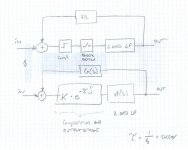
Eva and ChocoHolic, how do you model your amps. See drawing; would you say it’s a fair representation, of a self oscillating design including a 2. order output filter??
Where tau is the summed delay from comparator, deadtime, output stage delay, and switching frequency. This will give a large phase shift towards higher frequencies.
Oscillation frequency can then be found as with a normal feedback amplifier (180 dg, unity gain at the summing point).
/Baldin
But as you ChocoHolic, I would not judge it before hearing it. On the other hand I would guess it is actually very good ….. ML simply don’t make bad products!
Yes you could be right about the output inductors not being ferries, it could very well be a type of plastic former, making it an air coil in essence.
Eva and ChocoHolic, how do you model your amps. See drawing; would you say it’s a fair representation, of a self oscillating design including a 2. order output filter??
Where tau is the summed delay from comparator, deadtime, output stage delay, and switching frequency. This will give a large phase shift towards higher frequencies.
Oscillation frequency can then be found as with a normal feedback amplifier (180 dg, unity gain at the summing point).
/Baldin
Attachments
would you say it’s a fair representation, of a self oscillating design
I'm not they, but I wouldn't say. Natural sampling doesn't cause delay. Otherwise it's a usable approximation, but only at small signal levels and low freq. At high levels K become nonlinear, and the switching residuals start to go down to audio band.
BTW: fsampling=2*fswitching (at least as long as modulation index is small).
Pafi said:
Natural sampling doesn't cause delay.
Natural sampling introduces just enough delay to add 180 degrees of phase shift at a frequency of half the sample rate. Think about it; if a small signal ideal step suddenly appears at a switching amplifier's input, any output response cannot occur at least until the next natural sampling point.
Regards - a.s.
Greetings Pafi and analogspiceman
That is correct, but that is considering an ideal sampling system.
In a real PWM amp, there will also be a considerable propagation delay from input to output, caused by propagation delay in comparator, level shift (if used), mosfet driver and mosfet. Here we are talking in the order of 100 - 200 nS!
But I guess this is also just little enough for it to be considered in below the switching frequency, and a pure linear model can be used.
analogspiceman!
When you modell PWM with linear elements, then you must assure that signals don't violate shannon's theorem. A step signal is not a usable test-signal. Take a sinewave as input of the modulator with smaller (much smaller for clarity) freq then fs/2, and you will find that in the spectra of output signal the fundamental component will have perfectly zero phase-shift!
Sampling itself never introduces delay. What does (in mixed, discrete and continuous time systems) is zero order holder (or any other reconstruction filter)!
If you were right, total phase-shift in a self-oscillating amp at switching freq in the whole loop would be: 180 (invert) + almost 180 (LC LPF) + 180 (delay of sampling) + 36 (220 ns delay of miscellanous stages at fs=400 kHz) - 30 (phase shift of feedback network) = 540 degrees. Oops! This doesnt work. There should be 360 degrees of phase shift for oscillation.
When you modell PWM with linear elements, then you must assure that signals don't violate shannon's theorem. A step signal is not a usable test-signal. Take a sinewave as input of the modulator with smaller (much smaller for clarity) freq then fs/2, and you will find that in the spectra of output signal the fundamental component will have perfectly zero phase-shift!
Sampling itself never introduces delay. What does (in mixed, discrete and continuous time systems) is zero order holder (or any other reconstruction filter)!
enough delay to add 180 degrees of phase shift at a frequency of half the sample rate.
If you were right, total phase-shift in a self-oscillating amp at switching freq in the whole loop would be: 180 (invert) + almost 180 (LC LPF) + 180 (delay of sampling) + 36 (220 ns delay of miscellanous stages at fs=400 kHz) - 30 (phase shift of feedback network) = 540 degrees. Oops! This doesnt work. There should be 360 degrees of phase shift for oscillation.
How about modelling with LTSpice ?
If you just want to find the oscillation frequency of the self resonating system - then I would tend to say that Baldin's model should do the job, because in most systems the parameters of the output filter (for post filter feedback) combined with the complex feedback impedance are dominating the self oscillation.
But since there is cost free LTSpice and cheap fast PCs,
I am not modelling by hand anymore.
This does also allow to include dead time settings and resulting distorsions. Last but not least in the mean time many MosFet models with stunning good reality matching and still acceptable simulation times are disclosed for free use by multiple manufacturers.
So simulation is really offering great opportunities.
But of course still remaining some differences, especially if you are to lazy to put PCB inductances in your simulation. Also rail decoupling for super fast comparators, level shifters & MosFet drivers still offer good chances for surprises in reality.
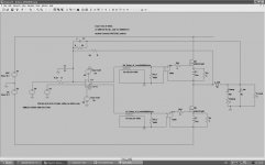
Just for inspiration a screen shot of a quite fundamental simulation of my simplest clocked class D approach.
This simulation is so nice that it even shows the limitations of my di/dt limiter. Even without external gate resistors, the internal gate resistance of the IRFB4321 is limiting the reaction speed of the di/dt regulation, causing a small Ugs overshoot. At very high currents this Ugs overshoot is growing to levels that may theoretically kill the MosFet....
Hungry for LTSpice now?
If you just want to find the oscillation frequency of the self resonating system - then I would tend to say that Baldin's model should do the job, because in most systems the parameters of the output filter (for post filter feedback) combined with the complex feedback impedance are dominating the self oscillation.
But since there is cost free LTSpice and cheap fast PCs,
I am not modelling by hand anymore.
This does also allow to include dead time settings and resulting distorsions. Last but not least in the mean time many MosFet models with stunning good reality matching and still acceptable simulation times are disclosed for free use by multiple manufacturers.
So simulation is really offering great opportunities.
But of course still remaining some differences, especially if you are to lazy to put PCB inductances in your simulation. Also rail decoupling for super fast comparators, level shifters & MosFet drivers still offer good chances for surprises in reality.
Just for inspiration a screen shot of a quite fundamental simulation of my simplest clocked class D approach.
This simulation is so nice that it even shows the limitations of my di/dt limiter. Even without external gate resistors, the internal gate resistance of the IRFB4321 is limiting the reaction speed of the di/dt regulation, causing a small Ugs overshoot. At very high currents this Ugs overshoot is growing to levels that may theoretically kill the MosFet....
Hungry for LTSpice now?
Attachments

I would tend to say that Baldin's model should do the job, because in most systems the parameters of the output filter (for post filter feedback) combined with the complex feedback impedance are dominating the self oscillation.
In baldin's original modell there is a whole 360 degrees of phase-shift only because of switching! OK, maybe you could say 360=0 at fs, but the modell have also 180 degrees of phase-shift at fs/2, etc...! This system wouldn't be stable with almost any kind feedback, while we know it's perfectly stable in reality!
(edit: I see, you already noticed it.)
in most systems the parameters of the output filter (for post filter feedback) combined with the complex feedback impedance are dominating the self oscillation.
I don't think so. Basic UcD wouldn't oscillate at all without delay (of level shifter, comparator, mosfet). (With an additional pole in the feedback it would have a well-defined oscillating freq without delay, but delay still would have a grate effect on fs.)
Pafi said:
....
I don't think so. Basic UcD wouldn't oscillate at all without delay (of level shifter, comparator, mosfet). (With an additional pole in the feedback it would have a well-defined oscillating freq without delay, but delay still would have a grate effect on fs.)
Oohps.. !
I must agree. In UcD the outputfilter is 2nd order, means its phase shift remains below 180deg. The Ucd feedback contains a D portion, which can just reduce the phase shift. If now the forward path would be ideal it won't oscilate.
Let's make a rough guess:
Oscilating fs: 200kHz
Delays of comp, level shifter and MosFets: 150ns
==> 150ns make about 10.8 deg phase shift.
Means self oscillation takes place at frequencies where the plot of phase shift vs f becomes already flat...
Looking like a system that would result in large tolerances for the oscilating frequency.
And yes, this is fitting to your statement that already small changes in delay times of the comp+driver+Mosfets do change the oscilation f quite remarkable.
Thanks for this eye opening discussion. Obviously pushing my ideas regarding selfres designs towards topologies with post filter feedback and
LC-feedback-network, in order to get very stable oscilating frequencies. Did you ever try such an arrangement?
Hi All
Yes you're right that 1/fs should be ommited, my mitake.
Yes I have done som simulations in LTspice, but not enough .... will try to get more familiar with the tool
I used to use Protel (simulation ok for normal analog design) and a very good design environment (integrated PCB), but it is no good for switching app, in my experience.
My class d amps have had to long a rest now ... time to get it moving again ... New Year is coming
Speaking of which ......
Happy New Year to all of you
..... time to prepare for a litle party

Baldin said:
In a real PWM amp, there will also be a considerable propagation delay from input to output, caused by propagation delay in comparator, level shift (if used), mosfet driver and mosfet. Here we are talking in the order of 100 - 200 nS!
But I guess this is also just little enough for it to be considered in below the switching frequency, and a pure linear model can be used.
For a UcD style amp switching at around 250kHz to 300kHz, that much delay contributes 10 to 20 degrees of phase shift at the operating frequency. For anything other than a rough first cut design this very much matters. -- a.s.
- Status
- This old topic is closed. If you want to reopen this topic, contact a moderator using the "Report Post" button.
- Home
- Amplifiers
- Class D
- To Clock or not to Clock!