Hi all,
these days I was considering building a PSU for High Power amplifiers.
As it is high power, I was considering the use of 3 phase power.
The interesting stuff would be, that in this experiment I would use a capacitive voltage divider to get the right voltages.
I was thinking about 1 way rectified 3 phase power which give me (EU)
+/- 320V DC symmetrical to the ground... (+/- 170V in the USA)
For the problem of the high voltage one usually would use a power transformer ( 50Hz or SMPS with higher frequency)
However I was thinking about using a capacitive voltage divider instead of a multi output transformer.
In order to decrease the needed capacitance values, the +/-320V (rectified, and poorly smoothed with say 50-100uF - so lets call it DC) should be switched with switches (IGBT?) thru a coil to a capacitive voltage divider at say 100kHz. This way the input current will be more sinus like...
Here comes an 1:1 ratio 100kHz transformer for isolation (well maybe even two for increase the power capacity - one for the high side and one for the low side)
Then one could get the individual 100kHz AC voltages from the capacitors and build the (so called) secondary rectifier and capacitors to get real (and now smaller) DC rails.
What do you think about it?
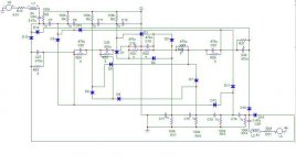
attached the theoretical shematics of the divider and "secondary" driven by two symmetrical 100kHz square wave generators.
Tamas
these days I was considering building a PSU for High Power amplifiers.
As it is high power, I was considering the use of 3 phase power.
The interesting stuff would be, that in this experiment I would use a capacitive voltage divider to get the right voltages.
I was thinking about 1 way rectified 3 phase power which give me (EU)
+/- 320V DC symmetrical to the ground... (+/- 170V in the USA)
For the problem of the high voltage one usually would use a power transformer ( 50Hz or SMPS with higher frequency)
However I was thinking about using a capacitive voltage divider instead of a multi output transformer.
In order to decrease the needed capacitance values, the +/-320V (rectified, and poorly smoothed with say 50-100uF - so lets call it DC) should be switched with switches (IGBT?) thru a coil to a capacitive voltage divider at say 100kHz. This way the input current will be more sinus like...
Here comes an 1:1 ratio 100kHz transformer for isolation (well maybe even two for increase the power capacity - one for the high side and one for the low side)
Then one could get the individual 100kHz AC voltages from the capacitors and build the (so called) secondary rectifier and capacitors to get real (and now smaller) DC rails.
What do you think about it?
attached the theoretical shematics of the divider and "secondary" driven by two symmetrical 100kHz square wave generators.
Tamas
Attachments
ttako!
This is unneccessarily complicated, and involves very hard problems (instead of solving them). If you already have a trafo, why would you use anything else for changing voltage?
A 1 way rectifier gives single +320V.
This is unneccessarily complicated, and involves very hard problems (instead of solving them). If you already have a trafo, why would you use anything else for changing voltage?
1 way rectified 3 phase power which give me (EU) +/- 320V DC symmetrical to the ground...
A 1 way rectifier gives single +320V.
Hi Pafi,
I know, it is not the easiest solution. First of all that was just an idea, how one could also use some unconventional technique for getting different voltages....
and for the 1 way rectifier: please note, that i meant using 6 diodes for 3 phase ( 2/ phase) in this case I think you get +/-320V symmetrical to the 0V...
Thanks,
Tamas
the only downer on this is compliance- there is no way you would get this passed en60065, there is no isolation from the mains and hence its potentially lethal- unless you use an isolating tx in the mains, then whats the point?-
oops read again and you mention isolation, just scanned and looked at schema!
oops read again and you mention isolation, just scanned and looked at schema!
- Status
- This old topic is closed. If you want to reopen this topic, contact a moderator using the "Report Post" button.