Hi,
I am trying to make a class-D amp,using IRS2092(S) and IRF6655 for my term here, and I am quite stuck at getting the amp to start working!
My design is based on recommended design by IAR. Here are the details:
(All voltages referred to ground)
1. The bus voltages are +/- 25 Volts
2. The voltage at COM pin is -24.8V
3. Voltage at CSD pin is +4.9V
4. Voltage at VSS pin is -6.9V
5. Voltage at VAA pin is +7.05V
6. Voltage at VREF pin is -7.14V
7. Voltage at OCSET pin is -20.3V
8. Voltage at DT pin is -23.5V
9. Voltage at VCC pin -12.8V
10. Voltage at VS pin is +2.44V
11. Voltage at VB pin is +16.9V
12. Voltage at CSH pin is +2.44V
13. Voltage at VSS pin is -6.9V
So far, I have gone by the "recommended operating conditions" column in IRS2092 datasheet and found that I meet the conditions for normal operation. For example, The V(CSD) voltage, referred to VSS is about Vth1, and that VBS (Voltage between VB and VS) is also above 10V. I can see that the comparator pin is working, as I can see the square waves generated by the OTA.
However, my HO and LO pins are firmly off, which beats me. Can anyone please help? I am attaching my schematics. At this point, I am bothered as much about performance as about getting the IRS chip to start!
This design is supposed to deliver only 40W to a 4-ohm load.
Would really appreciate suggestions.
Thanks
Devendra
Attachments
Hi Ouroboros,
Oh! I have added the ground connection. It did not help matters though. I see from the IRS2092 datasheet that voltage at CSD pin tells me the state of the chip, and I calculate that at the voltage that I have seen and provided here, the chip should be working normally.
Here is the updated schematic
Do you think I am wrong here?
Thanks for your time and patience.
Devendra Rai
Attachments
Devendra,
Try Removing R20. R20 and R21 are forming a voltage divider for the Opamp U2-A. with VCC+ = to -12.8V this means that you have -6.4V coming out of the opamp. This will make the rest of the circuit try to put out about (47/4.2)*-6.4~=-71.6V. One oddity I noticed is the Vref should be 5V above COM, but your vref is setting at -7.14 this puts it at around 17.66 and a current draw of 1.8mA out of that pin which is too high, the data sheet says it should be between .5mA and .8mA but the value of resistors you have for OCSET are good values that might mean there is something wrong with your chip. Try pulling R20, if that does nothing then try replacing the IRS2092 it's self.
Try Removing R20. R20 and R21 are forming a voltage divider for the Opamp U2-A. with VCC+ = to -12.8V this means that you have -6.4V coming out of the opamp. This will make the rest of the circuit try to put out about (47/4.2)*-6.4~=-71.6V. One oddity I noticed is the Vref should be 5V above COM, but your vref is setting at -7.14 this puts it at around 17.66 and a current draw of 1.8mA out of that pin which is too high, the data sheet says it should be between .5mA and .8mA but the value of resistors you have for OCSET are good values that might mean there is something wrong with your chip. Try pulling R20, if that does nothing then try replacing the IRS2092 it's self.
Devendra said:
Here is the updated schematic
Hello from Japan.
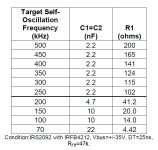
I am also planning to build IRS2092 amp. I checked your
schematic and found that your self oscillation frequency
is intended to 400KHz which is given form IRS's application
note AN-1138. I am attaching the table of frequency set up
from that document, herewith.
Related to this circuitry, C4(2n) and C7(1n) are in parallel in yours.
I don't know the suitable value of these capacitance, but the
reference designs don't use such big capacitors, usually 1n is
used.
Regarding to CSD voltage, I think +4.9V is enough to activate
the CHIP ENABLE.
Attachments
I would like to build a Class D too.
Do any one have a chance comparing IRAUDAMP7D with Hypex UcD180HG (with or without HxR).
Which one sounds better?
For UcDxxxHG, is it really worth to add the regulator HxR? Will it sound even better after adding them? Or, their purpose is only reducing noise.
For IRAUDAMP7D, I do not have the reference kit. But, from the datasheet, I think there is a mistake on figure 36 about full bridge. Near S300 DPDT, are the "bridge" and "stereo" labels in wrong position?
Do anyone think that can I use a balanced input for full bridge instead of inverting by op amp?
Thanks
Jackie
Hi,
I am trying to make a class-D amp,using IRS2092(S) and IRF6655 for my term here, and I am quite stuck at getting the amp to start working!
Thanks
Devendra
The irs2092 can be a minefield for those new to class d.
Decoupling is vital, not just around the 2092 but also around the mosfets b+/b- b+/gnd b-/gnd with 100nf. Care must be taken with the 12 volt vcc rail, I had noise on mine causing the 2092 to reset. I used a 100uf on this rail.
I found that I had trouble getting it to run with a 22uH inductor, I found a 30uh worked much better with less resetting on hard clipping.
Just to add to the fun I found some 2092's were susceptible to resetting while others werent even on the same pcb.
I found some got upset with hard clipping inputs and this was cured with a couple of 4v7 zeners across the analogue input.
You didn't use RC low pass filter in feedback, I did
Why do you have R18?
Also lower value are recomended for settings of IRS, there has to be some min current going via those resistors, at least 0.5mA for OCSET you have a lot less then that.
You have 45ns dead time, which is fine, but not what you resistors say (measured compared to gnd won't work here)
VAA and VSS can't be more then +/-6v, I used 5.1v zeners, and you have +/-7V (IC could be damaged already)
Vref is 5.1v compared to -Vcc, yours seems to be a lot higher
OCSET being -20V out of -25 V is totaly wrong, 5v is a little less then half of 12V (BTW you really should re-measure everything since most things are compared to -Vcc, like OCSET, Vref, DT,... and some to gnd, as in Vaa and Vss, CSD)
Last edited:
- Status
- This old topic is closed. If you want to reopen this topic, contact a moderator using the "Report Post" button.
- Home
- Amplifiers
- Class D
- IRS2092 Amp Design: Please help!