Looking for a simple durable design that'll work well in this app.
Page 23 BTL Sync.... -1 buffer (at least I think it's a buffer) to Vin channel 1
http://www.icepower.bang-olufsen.com/files/solutions/icepower125asx2_datasheet_1_1.pdf
I've done a lot of DIY transistor kits and designed and built a lot of vacuum tube amps.
Thanks
Page 23 BTL Sync.... -1 buffer (at least I think it's a buffer) to Vin channel 1
http://www.icepower.bang-olufsen.com/files/solutions/icepower125asx2_datasheet_1_1.pdf
I've done a lot of DIY transistor kits and designed and built a lot of vacuum tube amps.
Thanks
The circuit in the app sheet is to split the signal into 2 halves of opposite phase. That's what you need for the BTL arrangement.
You can do it with opamps, but you'll have to find the power somewhere. DON'T count on the aux supply on the PCB, it isn't reliable.
A transformer would do the trick nicely.....
Remember that the input impedance of this amp is low - about 10K, IIRC.
You can do it with opamps, but you'll have to find the power somewhere. DON'T count on the aux supply on the PCB, it isn't reliable.
A transformer would do the trick nicely.....
Remember that the input impedance of this amp is low - about 10K, IIRC.
The simplest way would be with a DRV134, but they like low source impedance (<600R). Here is how to do it wth op-amps.....
http://sound.westhost.com/project14.htm
My favorite is to use OPA1632/THS4131 driven with a good op-amp as a buffer.
http://sound.westhost.com/project14.htm
My favorite is to use OPA1632/THS4131 driven with a good op-amp as a buffer.
This thread is rather old but I'm having same requirement.The circuit in the app sheet is to split the signal into 2 halves of opposite phase. That's what you need for the BTL arrangement.
Anyone can advice if I can fed the ASX2 with balanced input signal and have it operated in BTL mode?
Tks
I've run them in BTL mode from a balanced source - no problem at all. If you have a balanced source of any kind you dont need a input buffer, but if you dont - you must build a buffer of course. I see no reason miniDSP with balanced out should not work directly connected to the ASX2 in BTL mode.
Be careful with what you pick, those boards input impedance falls drastically at high frequencies. I measured it and have plots here:
http://www.diyaudio.com/forums/class-d/192789-icepower-125asx2-measurements-mods.html
So whatever you build, it better have a low output impedance. I built an op-amp buffer stage and used the auxiliary power on the amp board to power it (I regulated and filtered the aux power)
http://www.diyaudio.com/forums/class-d/192789-icepower-125asx2-measurements-mods.html
So whatever you build, it better have a low output impedance. I built an op-amp buffer stage and used the auxiliary power on the amp board to power it (I regulated and filtered the aux power)
Hi Everyone -- long-time lurker and 1st time poster.
I've never built anything before unless it was made of wood, so there's my skill level. This site has always yielded good and/or interesting info which helped guide my hardware purchases, but I've never (yet) dived into an electronics project.
So, I don't know if anyone cares to help me with my ignorance (it's a big job!) but I'm wondering about the DIY possibilities of these 125asx2 modules. After reading the datasheet it seems easy enough to assemble a stereo version, but I'm confused about bridging them. I was under the impression it was a matter of a jumper to switch from SE to BTL, but That's obviously wrong. Is there a nutshell explanation someone can give me of what physically needs to happen to these modules to render them "BTL"? Does it take another version of the board entirely, or an add-on of some sort?
Hi Everyone -- long-time lurker and 1st time poster.
I've never built anything before unless it was made of wood, so there's my skill level. This site has always yielded good and/or interesting info which helped guide my hardware purchases, but I've never (yet) dived into an electronics project.
So, I don't know if anyone cares to help me with my ignorance (it's a big job!) but I'm wondering about the DIY possibilities of these 125asx2 modules. After reading the datasheet it seems easy enough to assemble a stereo version, but I'm confused about bridging them. I was under the impression it was a matter of a jumper to switch from SE to BTL, but That's obviously wrong. Is there a nutshell explanation someone can give me of what physically needs to happen to these modules to render them "BTL"? Does it take another version of the board entirely, or an add-on of some sort?
BLT means that the two channels will have to work 180 derees out of phase. To get them to do this, you must build a phase inverter circuit and feed the output from this to one of the inputs. The other input should recieve the original signal directly.
You will only get one BLT channel pr. ASX2 board.
Warm regards
\\\Jens
")
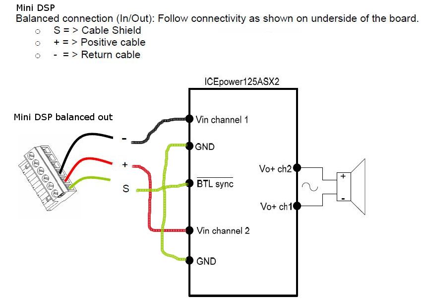
A few days ago i've finished my BTL mode signal header cable for my 125ASX2 with balanced input signal. Can someone tell me if this wiring is correct?
http://abload.de/image.php?img=btlwiring4psow.jpg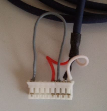
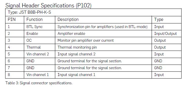
(As i've measured Pin 6+7 GND is bind together on the 125asx2 mainboard). On the pic: pin1 is on the left side.
The balanced signal comes from my miniDSP balanced. Test was ok, looks like it's workig but if i drop the miniDSP output signal level to 0, or near 0, i hear a tiny bit of background noise that can be heard a few inches from the speaker. This backround noise has always the same volume. If i increase the music level you don't hear it but at very low music volume you can hear the background noise.
I've heard in BTL mode the 125asx2 should be dead silent? So maybe my wiring is wrong or the miniDSP gives some backround noise to the icepower? Input signal to miniDSP is unbalanced, output from miniDSP balanced to 125asx2.
http://abload.de/image.php?img=btlwiring4psow.jpg


(As i've measured Pin 6+7 GND is bind together on the 125asx2 mainboard). On the pic: pin1 is on the left side.
The balanced signal comes from my miniDSP balanced. Test was ok, looks like it's workig but if i drop the miniDSP output signal level to 0, or near 0, i hear a tiny bit of background noise that can be heard a few inches from the speaker. This backround noise has always the same volume. If i increase the music level you don't hear it but at very low music volume you can hear the background noise.
I've heard in BTL mode the 125asx2 should be dead silent? So maybe my wiring is wrong or the miniDSP gives some backround noise to the icepower? Input signal to miniDSP is unbalanced, output from miniDSP balanced to 125asx2.
Last edited:
- Status
- This old topic is closed. If you want to reopen this topic, contact a moderator using the "Report Post" button.
- Home
- Amplifiers
- Class D
- Need input buffer design or ideas for icepower 125asx2 in BTL mode.