I am trying to evaluate before drawing the prototype PCB whether I have designed for too much output voltage ripple or not.
The smps is supposed to feed a pair of 200W UcD modules (not hypex, but very similar in design in all important areas). Both modules are fed from the same capacitor bank at the output from the SMPS, and are thus exposed to cross-talk (I dont know if this is a problem since I have not tested for it yet). The SMPS is supposed to work in an automotive environment, and I have calculated worst case temperature swing for the ESR of the output filter capacitors, which will give a worst case ESR-based ripple of 200mV, best case ESR ripple of 70mV, and a constant C-based ripple of 24mV. This totals to a worst case ripple of 224mV, and best-case of 94mV (less ripple the warmer it gets). The frequency of this ripple is 106kHz.
Is this too great an amount of ripple? I can meet all rms-ripple demands for the output filter with this little capacitance, and adding more capacitors to keep ripple down makes routing the pcb difficult. Handling rail pumping is not an issue since I have provided measures for dealing with that by way of an additional balancing smps.
The output filter is 50uH/680uF, Ton*Von/L is held constant at 3.46A by the control loop.
In addition to my calculations, I have 680uF capacitance per rail per amplifier module as well, but I have chosen not to include that into the calculation as the amplifier modules also might change in the future, and I want to have the option of applying filtering that might decouple this storage from the control loop.
If forced to, I think I can fit 2x680uF per rail before going out of PCB space, but that will also be at the expense of a few more cm^2 of current loop area :/
Any input on this?
Bruno Putzeys posted something about current in local capacitor http://www.diyaudio.com/forums/showthread.php?postid=662313#post662313
BWRX said:What is the PSRR of the modules at 106kHz?
I have no idea, I guess what I am curious about is how the feedback loop of the UcDs will handle this, and what kind of phase locking that might result. Also interested in whether beating might take place or not.
I actually managed to route in 2x680uF per side, so the ripple is expected to be only half of that during high output power, and lower at low output load (the ripple is calculated for the case when the output inductors are on the verge of going dry)
A variable frequency SMPS may work...
The variable frequency SMPS has been pushed by several companies in an effort to reduce EMI. The reasoning is that the resultant interference spectrum becomes spread and therefore the peak value is lowered.
However, the feedback loop may require some special considerations. The frequency change may have to be also limited.
You may want to do a google search on "Spread Spectrum Power Supplies"
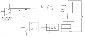
darkfenriz said:I think one could do it by asynchronous divide-by-2 circuit followed with a wide band PLL.
A divider eats most of a modulation, a PLL provides "clock" at startup, overdrive and other strange occasions, eats rest of modulation/jitter too.
What do you think?
From SG3525 datasheet:
"A sync input to the oscillator allows multiple units to be slaved or a single unit to be synchronized to an external system clock"
darkfenriz said:Anyone ever tried synchronizing SMPS to sefl-oscillating class D amp?
You would have a lot of trouble handling both clipping and startup. Note that oscillation does not start until some signal is applied to the amplifier. It becomes even more complex when you have several self oscillating channels sharing the same power supply.
In my experience, interference is negligible if things are done properly.
bjorge said:
From SG3525 datasheet:
"A sync input to the oscillator allows multiple units to be slaved or a single unit to be synchronized to an external system clock"
Yes, SG3525 may be a nice option here, but first one has to derive a relatively clean "clock" from the amp's PWM.
A PI filter (an extra LC after the filter caps) can be pretty effective if you need lower ripple. Much better than just putting more and more caps in parallell. The inductance required is pretty small actually.
Don't know if this is needed though, it's just a suggestion if you find out that you do need lower ripple.
Don't know if this is needed though, it's just a suggestion if you find out that you do need lower ripple.
Member
Joined 2003
FYI, the SMPS180 from Hypex uses a bit of a pi filter at the output. On each rail it has a 1000uF cap, then what looks to be a ferrite bead, then a 4700uF cap.
I did some research on using a CLC in a power supply a while back, and found that the second C is much more important than the first, which is verified by looking at the Hypex supply.
I did some research on using a CLC in a power supply a while back, and found that the second C is much more important than the first, which is verified by looking at the Hypex supply.
- Status
- This old topic is closed. If you want to reopen this topic, contact a moderator using the "Report Post" button.
- Home
- Amplifiers
- Class D
- smps voltage ripple for feeding UcD amplifiers