Iam trying to build a subwoofer amp using TDA8920BJ IC and I am trying to figure out some stuff from the schematic in the datasheet.
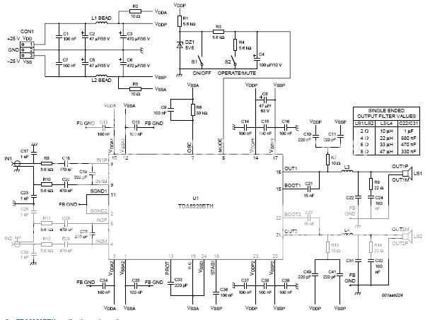
And I can't understand what resistors R14,R9 and cap C24,C32 do. Anybody know?
After looking around in application note for phillips class d amplifier they are sometimes omitted and sometimes only on one of the outputs. Both for BTL applications.
http://www.nxp.com/acrobat_download/applicationnotes/AN10436_1.pdf
Power Inductor
Thanks for all replies so far.
My highly speculative calculations show that the highest current will be around 7 A through the output network.
Anybody knows where to buy an inductor with ~25-16 uH that is capable of those currents? Best i've come up with are http://www.coilws.com/ but their shipping prices are horrifific.
Where do you buy your filter inductors?
guitar_joe said:heya,
where do you buy the TDA8920?
cheers
Changed my mind and bought them from ebay. 45$ for 10 pcs with shipping.
Hi Icko,
for the output inductor use a T106-2 toroid core and wind it by yourself.
There are plenty of commercial inductors with around 20uH and around 10A current capacity. The problem is that normally they are not suited for class-D.
The high switching freq (normally 300-400kHz) of a class-D amplifier need a output inductor with low losses at that frequency. Commercial inductors normally have too high losses at 400kHz and thus the output coil will dissipate a lot of power.
I have tried to use a Bourns 2300HT inductor, rated 22uH and 19A current; it was so hot that it melted its solder points...
If you use a T-106-2 core the losses are very limited,
for 20uH you need 38turns (AL=13.5nH).
If you need 7A wind 3x0.8mm diameter wires around the toroid.
You can get these parts easily on www.toroids.info and you can order them directly on www.kitsandparts.com.
I have already ordered some stuff from there, the shipping cost is low and in around one week you get what you need.
ciao
Thank You!
")
Where did you get that equation from? I mean how diameter of the wire and number of wires relate to the current.
Another question, when using multiple wires as you describe, you twist them before (to get a rope-like wire) you wind the toroid? Or just wire them flat.
38x3x0.8mm = alot of cuIf you need 7A wind 3x0.8mm diameter wires around the toroid.
Where did you get that equation from? I mean how diameter of the wire and number of wires relate to the current.
Another question, when using multiple wires as you describe, you twist them before (to get a rope-like wire) you wind the toroid? Or just wire them flat.
You can calculate exacly the wire diameter based on the current but you have to take into account the skin effect too.
Now I don't have the equation available but you can have an idea of the current capacitance of the wire on this link.
http://www.powerstream.com/Wire_Size.htm
A 0.8mm wire (AWG20) can be used for a DC current up to 11A. Here you are running at 400kHz so due to skin effect you use only a small portion of the wire area.
You are running your amp at +/-25V on a 4ohm load, this means that the maximum current will be around 6.3A + the ripple current in the output inductance.
By experience 2-3 parallel wires of 0.8mm diameter are enough.
I have used 2*0.8mm wires on a +/-40V and 4ohm (130Wrms) amp and a 5*0.8mm on a +/-55V 4ohm BTL amp (900Wrms) without any probems.
To wind the toroids don't twist the wires toghether it is harder because the twisted wire becomes less flexible. Electrically is more or less the same thing but practically is easier to wind them flat.
On a T106 toroid you can not wind 3*0.8mm*38t only on one layer, there is no enough place. Once you covered all the toroid with wires, start another layer until you have wound all the necessary turns.
ciao
icko, mag!
Ripple current is negligible compared to load current, and load current is quasi DC, so skin effect is negligible.
Practically 1*0.8 mm is perfectly enough. And this way distributed capacitance and stray inductance will be significantly less. Increasing of resistive loss is only 0.3 W (approx.) at full power, wich is insignificant.
I use 3*0.8 mm too... for 1 kW.
- Status
- This old topic is closed. If you want to reopen this topic, contact a moderator using the "Report Post" button.
- Home
- Amplifiers
- Class D
- output network