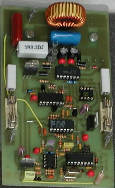
Could a discrete circuit be potentially better then a IC? What is the best IC / solution available? Note: i have a gate driving and level shifting circuit designed. The PWM circuit only drives a small signal fet.
Won't a 1% distorted triangle wave distort the audio output by 1%? A 1% triangle wave at 250khz is hard to get.
Won't a 1% distorted triangle wave distort the audio output by 1%? A 1% triangle wave at 250khz is hard to get.
Won't a 1% distorted triangle wave distort the audio output by 1%?
Maybe, or may not. It depends on the type of distortion, and also on the feedback. If the distortion changes one side of the signal in such a way that changes the other side in the opposit direction, then the distortion in audio is much smaller then the one in triangle.
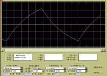
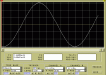
With the attached "triangle" wave...
Attachments
If the square wave is near perfect and the capacitor charges and discharges in a linear fashion that would make for a very precise triangle wave.
http://members.aol.com/sbench102/caps.html
Paper/oil, polycarbonate, polypropylene, or polystyrene should work well?
http://members.aol.com/sbench102/caps.html
Paper/oil, polycarbonate, polypropylene, or polystyrene should work well?
Hi Pafi!
Distortion can`t be removed even with feedback. It can only be reduced, depending on the open-loop gain, at the desired frequency.
By the way, don`t you think the feedback with infinite harmonics with their sidebands, what remainded from the square wave can cause harmonic distortion? I say it can, because there's sampling at the triangle comparation. But I'm not sure about it.
Gyula said:Hi Pafi!
Distortion can`t be removed even with feedback. It can only be reduced, depending on the open-loop gain, at the desired frequency.
Gyula!
Who said any contradictionary?
By the way, don`t you think the feedback with infinite harmonics with their sidebands, what remainded from the square wave can cause harmonic distortion?
What do you mean? There are many different cases. The extremely simplest case: quasy DC modulating signal, perfect triangle wave. In this case there is no distortion, it can be verified in both time and frequency domain. But in case of high frequency modulating signal (in practice ftriangle/fmod<=5..10) the mathematical analysis suddenly becomes very difficult. There are different type of PWM methods (main groops: naturally sampled, and periodically sampled PWM) and they have distortion without feedback already, but very different kind of distorton: periodically sampled PWM have harmonic distortion, but naturally sampled PWM have non-harmonic distortion! And we could start to analyse feedback after this, but linear assumptions are unusable if you suspected a nonlinear behaviour ("feedback makes distortion"). Not simply the amount of feedback, but the exact way of feedback determines closed loop distortion. For example: delay in feedback loop is evil, especially with multi-level PWM. This area of researches deserves not just a post, but a big topic. But to take a shortcut: experiments tell that feedback decreases distortion significantly, however sometimes not as much (1/loop gain) as we expect.
Prof. Halász Sándor had an interesting article about PWM distortions in IEEE in the end of 70's, but now I can't find it. There is a list of his publication, but I guess it's not full.
http://www.vet.bme.hu/mts/publ/halasz_sandor.htm
Yes, closing the loop inPWM does indeed introduce THD that wouldn't be there using an ideal PWM modulator without NFB.
In most cases the contributions of THD through non-idealities of the circuit is much higher than the contribution of the carrier being fed back.
For very-high quality switching amps this is the limiting factor however. And there are inventions to reduce this. An example is a circuit by Bruce Candy that is used for the Halcro multichannel PWM amps (patent is not hord to find) which do indeed seem to have exceptional THD figures.
There is this interesting paper on this subject written by Omar Hawksford:
http://www.essex.ac.uk/dces/researc...ocs/J51 Switching amplifiers and feedback.pdf
One very interesting principle is using a "perfect" PWM modulator whose output is subtracted from the scaled output of the actual amplifier. Only the difference between these is actually distortion and is therefore used for NFB.
Regards
Charles
In what conditions?Yes, closing the loop inPWM does indeed introduce THD that wouldn't be there using an ideal PWM modulator without NFB.
Pafi!
If you sample a signal, the spectra of the continuous signal will be overlapped with itselfs' shifted images. Thus the synchronous sampling effects sidebands in the baseband came from the carrier harmonics' sidebands. My thesis had cancelled this effect with a technique which I want to patent as wrote earlier.
I think this is also the case with analogue PWM because of the triangle comparation caused sampling.
Just think it over, you compare the input signal with a nonlinearly generated output. The feedback contains all the output stage nonlinearities, the modulation caused by the power supply voltage variations applied to the PWM spectra, which contains switching harmonics with them sidebands what are transposed to the baseband with the synchronous sampling. Just try to mix the control theory with signal processing when you think about it. Fundamentally everything is about the Fourier transform and Nyquist criteria in the two fields.
So, as a summary the controller will not control for the difference of the nonlinearly amplified baseband output and the input signal, but for some harmonics injected to the baseband with the sampling too. Thus the harmonics what are transposed from carrier harmonics effect as they were in the input signal already. You can put the disturbing source also to the input in a theoretical model, with a nonlinear output stage without switching harmonics and their sidebands.
Thus the synchronous sampling effects sidebands in the baseband came from the carrier harmonics' sidebands.
I can't decode this sentence. I don't know your modell what you are thinking in. Could you tell me it first? I had a question:"What do you mean? There are many different cases..."
The feedback contains all the output stage nonlinearities, the modulation caused by the power supply voltage variations applied to the PWM spectra, which contains switching harmonics with them sidebands what are transposed to the baseband with the synchronous sampling. Just try to mix the control theory with signal processing when you think about it.
Mixing theories wich are based on contradictionary conditions (PWM: nonlinear, control theory: linear) is not a simple task! If you managed to make any result this way, then tell it, but please don't tell me hints about how to think!
And mixing many different type of imperfections... Oh my God! I don't even try to think about the result!
Fundamentally everything is about the Fourier transform and Nyquist criteria in the two fields.
Yes, if you oversimplify things.
So, as a summary the controller will not control for the difference of the nonlinearly amplified baseband output and the input signal, but for some harmonics injected to the baseband with the sampling too. Thus the harmonics what are transposed from carrier harmonics effect as they were in the input signal already. You can put the disturbing source also to the input in a theoretical model, with a nonlinear output stage without switching harmonics and their sidebands.
Sorry, I don't understand you! (I don't even know what is "control for", etc...)
But otherways:
Do you really think to know in frequency domain what a PW modulator does with the full spectra of output signal of itself? For me it's absolutely impossible (without simulation). I know only one thing about it: with low freq modulating signal there is no distortion. If I understand some of your sentences well, you said that distortion comes from sidebands. But sidebands have the same energy with low freq modulating signal! Don't they have to make the same distortion, if your theory is correct?
If you sample a signal, the spectra of the continuous signal will be overlapped with itselfs' shifted images
What kind of sampling? Uniform?
What is "a signal"? Is it BW limited to fs/2 ? What is "shifted image"? Lower sideband of carrier can possibly overlap baseband, but only if shannons rule is broken. Wrong way..
Or naturally sampling (of PWM)? There is no "shifted image", but a much complicated side-band, very similar to phase modulation. I have no idea how to make any conclusion based on such a complicated signal. Your simple "thus" replaced a huge deduction chain.
Amazing!
I mean, not the fact that PWM feedback have some distortion, but the article!
Pafi!
Sorry, I didn't understand these things, could you describe them again?:
You should consider this: "The feedback contains all the output stage nonlinearities, the modulation caused by the power supply voltage variations applied to the PWM spectra, which contains switching harmonics with them sidebands what are transposed to the baseband with the synchronous sampling.". Not in time, but in frequency-plane, and it will not be so difficult.What is "a signal"? Is it BW limited to fs/2 ?
You can derive Fourier-series for this purpose, and then you should apply the sampling theory.Do you really think to know in frequency domain what a PW modulator does with the full spectra of output signal of itself? For me it's absolutely impossible (without simulation).
I used the word of control because of the control theory English denomination.(I don't even know what is "control for", etc...)
Sorry, I didn't understand these things, could you describe them again?:
Or naturally sampling (of PWM)? There is no "shifted image", but a much complicated side-band, very similar to phase modulation.
But sidebands have the same energy with low freq modulating signal! Don't they have to make the same distortion, if your theory is correct?
There are many different cases...
please don't tell me hints about how to think!
Oh my God! I don't even try to think about the result!
I ask you for 3rd (and last) time to tell me what are you talking about!
- I asked you a yes or no question.
- You should not give me advices. Especially not an advice what tell me jump to the middle of your speech in order to know what you could mean in the beginning! This is an unsuitable way of thinking, at least for me. You should put down the principles of your theory prior to build on them!
Have you done it? Have you draw your conclusions based on it?
So do you implicitely tell me you assumed uniform sampling? (Uselessly I asked you about this.)
And then I should apply inverse FFT, apply PWM in time-domain, and FFT again, right? Because PWM is cannot be described in fequency domain! Have you done these all? Or do you know a simple analitic description of PWM in freq. domain? Please tell us too!
And finally: why did you assume uniform sampling? Is it usual in analog PWM? (This topic is about analog PWM!) Or does it have a significant benefit over natural sampling?
I didn't ask you "why...". I asked the meaning of "control for", and still I don't know what does it mean. In your sentence "control (for)" seemed to be a verb+auxilary, while "control theory" is a noun, so it doesn't fit here.
Again? Does repeating makes them clear for you? Interesting. For me it doesn't work. Describe? What? The sentences? The words? Sorry, unless you ask precisely, I can't answer!
I wrote some of them. Take what is true for your modell! Or simply describe your modell! Learn it from Omar Hawksford, he described his modell precisely!
You should consider this: "The feedback..."
- I asked you a yes or no question.
- You should not give me advices. Especially not an advice what tell me jump to the middle of your speech in order to know what you could mean in the beginning! This is an unsuitable way of thinking, at least for me. You should put down the principles of your theory prior to build on them!
You can derive Fourier-series for this purpose
Have you done it? Have you draw your conclusions based on it?
and then you should apply the sampling theory.
So do you implicitely tell me you assumed uniform sampling? (Uselessly I asked you about this.)
And then I should apply inverse FFT, apply PWM in time-domain, and FFT again, right? Because PWM is cannot be described in fequency domain! Have you done these all? Or do you know a simple analitic description of PWM in freq. domain? Please tell us too!
And finally: why did you assume uniform sampling? Is it usual in analog PWM? (This topic is about analog PWM!) Or does it have a significant benefit over natural sampling?
I used the word of control because of the control theory English denomination.
I didn't ask you "why...". I asked the meaning of "control for", and still I don't know what does it mean. In your sentence "control (for)" seemed to be a verb+auxilary, while "control theory" is a noun, so it doesn't fit here.
Sorry, I didn't understand these things, could you describe them again?:
Again? Does repeating makes them clear for you? Interesting. For me it doesn't work. Describe? What? The sentences? The words? Sorry, unless you ask precisely, I can't answer!
There are many different cases...
I wrote some of them. Take what is true for your modell! Or simply describe your modell! Learn it from Omar Hawksford, he described his modell precisely!
Pafi!

Yes?- I asked you a yes or no question.
It had been done by many people. You can find it for example in Karsten Nielsen's Ph.D. thesis. Or in mine, it's in the I building's library.Because PWM is cannot be described in fequency domain!
No, I told that I assume the transposing also happens with analog PWM, because of the triangle comparation caused sampling.tell me you assumed uniform sampling?
I thought applying this sentence to a controller which receives error signal, what is derived with subtracting of the input and the fed-back output signal, to form the control signal of the output, in order to minimize the error signal."control for", and still I don't know what does it mean
Think about a simple fed-back analog Class-D as a model.Or simply describe your modell!
- Status
- This old topic is closed. If you want to reopen this topic, contact a moderator using the "Report Post" button.
- Home
- Amplifiers
- Class D
- Pulse Width Modulation Circuits


