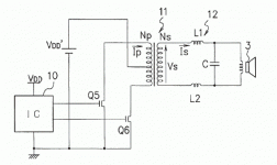
It is theoretically possible to build such an amplifier but the technical requirements for the transformers wouldn't give any advantages over ANY other amp topology.
Apart from that this has been discussed in web forums etc so many times that it shouldn't be patentable in the first place.
Regards
Charles
Apart from that this has been discussed in web forums etc so many times that it shouldn't be patentable in the first place.
Regards
Charles
In patent #6844777, the key is fig.1 to fig.2. Full bridge classD is being isolated by a transformer. If fig.1 is working at 400khz, then the transformer in fig2 should be built by -2 material (maybe T130-2).
Then the carrier is eliminated by L-C like usual.
Then we can move to fig.3, the push-pull one.
At first glance, it seems to be working.
But when I experiment with transformer working with very narrow (or very wide) duty cycle, the weakness of transformer appear. I cannot fool the Volt-Second product of a quadrant.
I built an xformer Class D
I tried similar in the lab once. Used a MAX4295 open-loop Class D amp, driving N FETs. It dis work, doing aabout 4 watts into 8ohms at 1kHz or so. Anywhere below that it died, because this becomes close to DC flowing through the core.
With a large enough core it could be improved. it should have some feedback to correct for FET, voltage and xformr non linearities.
An alternative is to reverse the current in the transformer by having active rectifiers. This way no DC in the core.
Hi, thespeakerguy,
That's an important restrictionAnywhere below that it died, because this becomes close to DC flowing through the core.
Could you tell more about this?An alternative is to reverse the current in the transformer by having active rectifiers. This way no DC in the core.
In order to work the x-former would need to work from the lowest audio frequency up to higher than the carrier frequency. This would be extremelly difficult to build and also be bulky and espensive.
That's why I said there would be absolutely no advantage to it.
Regards
Charles
That's why I said there would be absolutely no advantage to it.
Regards
Charles
You would be able to sell something like this to the musical amplifier industry. Just say the transformer is for "warmth". 
http://www.warwickbass.com/amps/JHpoweramps.htm

http://www.warwickbass.com/amps/JHpoweramps.htm
Re: I built an xformer Class D
How?
If there is no low frequency through core, then you have to store energy somewhere. You will probably end up with synchronously rectified SMPS + PWM amplifier equivalent this way.
thespeakerguy said:
An alternative is to reverse the current in the transformer by having active rectifiers. This way no DC in the core.
How?
If there is no low frequency through core, then you have to store energy somewhere. You will probably end up with synchronously rectified SMPS + PWM amplifier equivalent this way.
I remember that a variation of Cuk converter can make bidirectional energy transfer. Patent#4186437. http://ece-www.colorado.edu/~rwe/papers/Powercon5.pdf
BTW, what is this patent about? #7057905
BTW, what is this patent about? #7057905
- Status
- This old topic is closed. If you want to reopen this topic, contact a moderator using the "Report Post" button.
- Home
- Amplifiers
- Class D
- Is this really working?

