Hello! I have nothing to say that my English is not good.
I have some small doubts, always caught my attention Class D amplifiers, however, the few diagrams eh found on the Internet that require the IC IR2110, IR2111, and so are my doubts: Is there any alternative to this IC? Will there be a way to make a more simple design with common components?
I thank in advance all the help I can give
There are no high-performance P-channel MOSFET with Vds ratings above 100V, and the ones rated at 100V or less exhibit too high Rds-on and charges/capacitances in comparison with N-channel devices.
You get increased performance and efficiency in return for the complexity of high side drive.
You get increased performance and efficiency in return for the complexity of high side drive.
lumanauw said:I'm blowing high/low mosfet driver like popcorn here. They seems so fragile. What's the secret to work with these IC's during development/experiment stage?
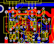
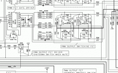
Could you show us the PCB layout and the schematic of the circuit that is so prone to blowing IR2xxx?
And where is the ground plane? 
The bootstrap capacitor is by far too small for audio class-D
The low-side current sense resistor is in the gate drive loop and in the HB/HS clamping loop


You clearly have some good keys for success
I place all my gate driver ICs and modulators in daughter boards and I use continous ground planes. I would never sense the current in that way, too. All this is for good reasons...
BTW: My methods may seem crazy, but I've just measured over 94% efficiency on a two-stage 120V 60Hz sinewave inverter at 2000W output. It uses IR2113 and I have not blew a single one during the whole development.
The bootstrap capacitor is by far too small for audio class-D

The low-side current sense resistor is in the gate drive loop and in the HB/HS clamping loop


You clearly have some good keys for success
I place all my gate driver ICs and modulators in daughter boards and I use continous ground planes. I would never sense the current in that way, too. All this is for good reasons...
BTW: My methods may seem crazy, but I've just measured over 94% efficiency on a two-stage 120V 60Hz sinewave inverter at 2000W output. It uses IR2113 and I have not blew a single one during the whole development.
Hi, EVA,
Why is when I blow the output mosfet, the driver always broken too? In experimental stage, how to preserve the UCC27200 whenever the output mosfet is blown away?
Why is when I blow the output mosfet, the driver always broken too? In experimental stage, how to preserve the UCC27200 whenever the output mosfet is blown away?
Do you mean the Vss for the UCC27200 should be taken after the current sensing resistor?The low-side current sense resistor is in the gate drive loop and in the HB/HS clamping loop
lumanauw said:Hi, EVA,
Why is when I blow the output mosfet, the driver always broken too? In experimental stage, how to preserve the UCC27200 whenever the output mosfet is blown away?
Do you mean the Vss for the UCC27200 should be taken after the current sensing resistor?
The driver is probably blowing up first. Then the MOSFET fail too. You don't need such a fast driver for 300Khz class D, it's completely overkill.
Concerning the Vss connection point, isn't the reply obvious enough?
ratmayor said:hello! ask for the IC and thought that they spoke in Japanese or in another language rare, there is no alternative use common components such as BJT's or CMOS?
Consider things from a different point of view: You won't be able to produce class D stuff until you understand our dialogs. When you don't understand the circuits in detail, you are likely to blow dozens of ICs and MOSFET without going anywhere.
Hi, EVA,
Thanks for the tips
I'm using floating 12V to make -VCC+12V (supply for gate driver). If the level shifting point, gate driver gnd, all placed after current sensing resistor, then this floating 12V also should be connected after this current sensing resistor too? What happens if this resistor fails?
Current sensing after inductor? Nice idea. Then the feedback point should be moved after this resistor, I think. Needs bidirectional current sensing?
Hi Lumanau,
parasitic resonances tend to kill the drivers.
You can have killed drivers even with surviving Fets...
Do you have screen shots of your gate signals at hard switching conditions? Please note these resonances are fast (typically 10MHz...100MHz), so you need a fast scope.
Ratmayor,
how about IRS20955.
IR is basically a good adress for high side drivers.
For higher voltages there is something with reasonable accuracy coming from Infineon:
http://www.infineon.com/cms/de/product/channel.html?channel=ff80808112ab681d0112ab6a547004ac
Hey Workhorse, Fredos,...
where are you? The Infineon driver should match to your normal voltage needs... ;-)
Eva said:
You don't need such a fast driver for 300Khz class D, it's completely overkill.
I do not fully agree.
As long as one is just struggling to get a D amp running, you are right.
But when you want really low THD, suddenly the ns-precision for gatesbecomes quite helpful. (And of course a reasonable modulator and low THD output filter...)
The UCC27200 seems to be a nice device, except missing shut down functions and quite low voltage ratings.
Until today I blow almost 20pcs of this UCC27200 and 20FDP3652. I feel tired with this experiment.
They are not blown by themselves, but my mistake. Sometime I touch something, sometime a cable snap, sometime I solder something when there is still voltage in the PCB, sometime the through-hole/track ruined (too many soldering+desoldering), etc. All resulted in blown UCC and FDP. Very fragile for experiment, unlike the discrete design. I'm relaxing for now
I agree with Chocoholic. Even if the switching frequency is only 400khz (max), better parts make better audible sound. I try to use TL3116+UCC27200+FDP3652, with very narrow dead time, the sound is very good.
My finding : UCC27200 is very hot. Better use the thermal pad one. Funny, the high-side gate resistor is much hotter than the low side gate resistor (I use 10ohm). Why is this?
parasitic resonances tend to kill the drivers
Yes and there is one more possibility to kill them:
If you feed the drivers with input signals having "dirty transitions" i.e. ones that look similar to contact bouncing.
This signal degradation might not even be visible at the driver's outputs but they will lead to increased losses. I don't know by what degree a 2110 is prone to this (some drivers have protection logic against this) but I once definitely killed some TSC44xx this way.
Regards
Charles
If high side gate resistor gets hotter than low side one while the amplifier is idle, there is something really wrong with the circuit. Either:
- High side drive signal is bouncing
- Low side series inductance is much higher
- High side supply voltage is higher
Are you using an UcD style modulator?
- High side drive signal is bouncing
- Low side series inductance is much higher
- High side supply voltage is higher
Are you using an UcD style modulator?
- Status
- This old topic is closed. If you want to reopen this topic, contact a moderator using the "Report Post" button.
- Home
- Amplifiers
- Class D
- Alternative for IR2xxx series

