Hi All,
as promised in my other thread about IRS2092 I will send you all the documentation about my new design with IRS2092 and IRFB4227.
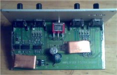
It is a 12V powered stereo car amplifier delivering more than 120Wrms on 4ohm. It includes a premaplifier section with selectable high pass filter and a low pass filtered output to drive my big amp delivering 900Wrms 4ohm BTL on the subwoofer.
Any suggestions or comments will be highly appreciated.
ciao
-marco
as promised in my other thread about IRS2092 I will send you all the documentation about my new design with IRS2092 and IRFB4227.
It is a 12V powered stereo car amplifier delivering more than 120Wrms on 4ohm. It includes a premaplifier section with selectable high pass filter and a low pass filtered output to drive my big amp delivering 900Wrms 4ohm BTL on the subwoofer.
Any suggestions or comments will be highly appreciated.
ciao
-marco
Attachments
Hi
I have nothing but respect, but why did you take wire from battery all over the board, why didn't you make holes on other side, and put input on other side too? that way you wouldn't have power cables going all over the board... And why did you make it for only +/- 30, I mean you would make it for +/-50 and have lot of power in reserve, you would be far from clipping at any time
You really did good you at this amp too
Hi Luka,
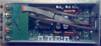
the original plan was with the input board on the other side but,
for mechanical reasons, the PCB hit the output class-D inductors and so I can not close the box.
I have put it on the other side just for this. The input are on the same side on the filter board to avoid running low level signal cables all around the box. There is just a short connection with a twisted pair from the RCA plug to the PCB.
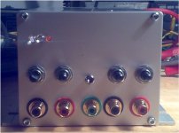
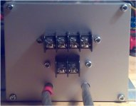
Battery cables are on the back side because doing like this the front panel is already full, so I prefer to use the back side.
About power supply:
The voltage is ajustable, with the current trafo I can go up to +/-48V. Now it is regulated at 37V. The problem is that with such high voltage the output power will be something around 250Wrms. The amplifier itself can handle that power but the SMPS I don't know. I have tried it with continuous 300W load with no problem but I don't know (and I don't want to know...) whats happens with more.
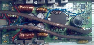
There is no heatsink for the power devices, I just use the aluminium box. Everything stays pretty cool at 120+120W but what happens at 250+250W???
This amp will be used for the front mid high section of my car stereo. It will drive a 16.5cm woofer and a tweeter installed on the front door. I don't think that such speakers will last too much with 250W.
ciao
the original plan was with the input board on the other side but,
for mechanical reasons, the PCB hit the output class-D inductors and so I can not close the box.
I have put it on the other side just for this. The input are on the same side on the filter board to avoid running low level signal cables all around the box. There is just a short connection with a twisted pair from the RCA plug to the PCB.
Battery cables are on the back side because doing like this the front panel is already full, so I prefer to use the back side.
About power supply:
The voltage is ajustable, with the current trafo I can go up to +/-48V. Now it is regulated at 37V. The problem is that with such high voltage the output power will be something around 250Wrms. The amplifier itself can handle that power but the SMPS I don't know. I have tried it with continuous 300W load with no problem but I don't know (and I don't want to know...) whats happens with more.
There is no heatsink for the power devices, I just use the aluminium box. Everything stays pretty cool at 120+120W but what happens at 250+250W???
This amp will be used for the front mid high section of my car stereo. It will drive a 16.5cm woofer and a tweeter installed on the front door. I don't think that such speakers will last too much with 250W.
ciao
Hi
I understand, but amp could still runn at higher voltage, you don't need to use all the power, just as much you need, and that AL box should be more then enough for cooling... I don't know why you put such big ones on other amp, it is not AB amp, and you don't drive 1R loads, so it doesn't heat at all, not even close to heat those heatsinks up...what do you think?
I understand, but amp could still runn at higher voltage, you don't need to use all the power, just as much you need, and that AL box should be more then enough for cooling... I don't know why you put such big ones on other amp, it is not AB amp, and you don't drive 1R loads, so it doesn't heat at all, not even close to heat those heatsinks up...what do you think?
Hi Luka,
you are right, the heatsink on the 900W amplifier was a bit overkill. It was my first design with class_D and it was hard to believe for me that such an high powered amplifier almost doesn't heat up at all.
About the maximum power I prefer to limit it trough the rail voltage. Having a 250W amp driving a small 16cm speaker will for sure blow it up shortly.
I have installed the two amps in my car and, believe me, still 120+120W + 900W on the sub is loud as hell. I don't think I need more power....
If you try to build my amps please let me know what you are doing, especially about post filter NFB. I have put it as an option on the PCB but never had time to test it. It is possible that nothing is running or even that everything blows up, who knows?
ciao
- Status
- This old topic is closed. If you want to reopen this topic, contact a moderator using the "Report Post" button.
- Home
- Amplifiers
- Class D
- Another amp with IRS2092