theAnonymous1 said:The only thing I did differently with the TPA3106D1 board is put one inductor on each side of the board and I used 1uF WIMA MKS capacitors for the output filter instead of 1uF X7R ceramics. Could either of those things cause this problem, or could it just be a layout issue?
Try eliminating the possibilities one by one. Swap out the film caps for the ceramics and see what happens. If that doesn't change anything then try connecting one of the inductors to the board with short wires (~0.5 inch) and move the inductor around.
Very nice prototypes by the way
")
BWRX said:
Try eliminating the possibilities one by one. Swap out the film caps for the ceramics and see what happens. If that doesn't change anything then try connecting one of the inductors to the board with short wires (~0.5 inch) and move the inductor around.
Very nice prototypes by the way
Thanks Brian. I tried both changing the caps to ceramics and moving the inductors around with no change in temp.
The inductors heat up to around >100F with a room temp of 76F. Is that considered "hot"? Should I even worry about it?
A scope would make a really nice fathers day gift. Would it count as a gift if I buy it for myself?

EDIT: I forgot to mention the idle current draw is 50mA. The datasheet says it should be 14-17mA.
Without the inductors connected the idle current draw is 16mA.
EDIT: When the ground point between the two 1uF caps is removed the idle current is normal. As soon as it is connected it goes back up to 50mA.
EDIT: When the ground point between the two 1uF caps is removed the idle current is normal. As soon as it is connected it goes back up to 50mA.
An externally hosted image should be here but it was not working when we last tested it.
Oops.
Well, I found one major issue that fixed some of the problem. I had the MASTER/SLV pin driven LOW this whole time, meaning it was in slave mode, accepting a clock frequency on the SYNC pin.
I soldered a jumper wire from the MASTER/SLV pin to VREG and now the current draw is only 32mA instead of 50mA. The inductor temp is down to <90F.
I'm thinking the other problem is my layout. I didn't bother keeping the AGND and PGND seperate. I think I was so tired when I made it that it didn't even cross my mind that I should have.
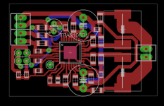
I finished my new layout. Doing the layout the way I do is very time consuming as everything is laid out manually; no nets at all. It's a royal PITA, but I can maximize the layout for how I hand make my PCBs.
I kept the AGND and PGND separate this time. They connect at one point; the thermal pad. Hopefully the 3 hours I spent on this was worth it.

I kept the AGND and PGND separate this time. They connect at one point; the thermal pad. Hopefully the 3 hours I spent on this was worth it.
Finished the new board. This one has an idle current draw of 32mA like the other one after I fixed the oscillation problem. I feel better about the layout on this one at least.
An externally hosted image should be here but it was not working when we last tested it.
An externally hosted image should be here but it was not working when we last tested it.
An externally hosted image should be here but it was not working when we last tested it.
kenpeter said:You didn't seem to leave yourself room to drill holes for standoffs.
Many components perhaps too close to the edge for snap track.
What was your plan? Or is this only for the bench?
Zip-ties!
I don't even have any extra standoffs on hand, so holes for them would do me no good.
Looking at the middle pic with the board on its side; I figure one tie around the PCB where the inductors are, and then one around the large electrolytics.
I think I will do dual mono-blocks with these. There are some really small 19v laptop SMPS available I plan to power them with.
I got a wacky wacky abuse to try... Gotta look through the
scrap for one with an old rev chip or eval board with some
cosmetic defect, nobody will care if I blow one of those up.
If it works, I might then try with a current rev board.
I got a pair of RCA 814 directly heated transmitter tubes.
I want to try them for audio output. Filaments need 10V
at 3.25A, and I hear bad things can happen to one end
of a directly heated filament after extended periods DC?
I am no fan of filament hum to try plain old AC. They do
light up with a bright golden glow like the 32.5W bulbs
they are, with DC on my Agilent bench supply.
Suppose I take a clean ultrasonic 50KHz sine wave instead?
From a Wien Bridge or whatever... And pump that through
one of TI's tough little Class-D amps with a real high frame
rate? The filament would then be about a 3 ohm BTL load?
Wonder if output inductors would be an issue at 50KHz?
TI may have some more appropriate part# to suggest?
I'll discuss this tomorrow (if an engineer has time) before
I move any further. I can still breadboard a Wien Bridge in
anticipation of some future experiment.
przem said:Hi
Currently i'm making pcb layout for tpa3106d1. I have noticed that you connected Vcc to Fault and Mute through a resistor - could you please explain why?
And what's the cap between INP and INN for?
Btw. How is the sound from this little baby?
If you look really close you will see that the Fault pin is actually connected to the Mute pin. This way when there is a Fault condition it will pull Mute high and mute the amp. The 100k to ground on the Mute pin is to pull it low when there is no fault condition.
The cap between INP and INN is a 10nf NP0. I was just experimenting and it isn't required.
I really like the sound of this amp. Plenty of punch and very clean. I suggest using it with the lowest gain setting though as the the background noise increases quite a bit with a higher setting.
I haven't built the other channel yet due to a recent move and broken laser printer; plus I need to order some parts from digi-key.
kenpeter said:I got a wacky wacky abuse to try... Gotta look through the
scrap for one with an old rev chip or eval board with some
cosmetic defect, nobody will care if I blow one of those up.
If it works, I might then try with a current rev board.
I got a pair of RCA 814 directly heated transmitter tubes.
I want to try them for audio output. Filaments need 10V
at 3.25A, and I hear bad things can happen to one end
of a directly heated filament after extended periods DC?
I am no fan of filament hum to try plain old AC. They do
light up with a bright golden glow like the 32.5W bulbs
they are, with DC on my Agilent bench supply.
Suppose I take a clean ultrasonic 50KHz sine wave instead?
From a Wien Bridge or whatever... And pump that through
one of TI's tough little Class-D amps with a real high frame
rate? The filament would then be about a 3 ohm BTL load?
Wonder if output inductors would be an issue at 50KHz?
TI may have some more appropriate part# to suggest?
I'll discuss this tomorrow (if an engineer has time) before
I move any further. I can still breadboard a Wien Bridge in
anticipation of some future experiment.
Put a capacitor across the filament, an inductor in series and apply a square wave. The waveform at the filament will be sine like. You will have to choose component values carefully so that the LC filter removes enough high frequency components and the filament resistance when hot provides enough damping to the filter. That's all. Electronic ballasts for fluorescent lamps work much in the same way.
theAnonymous1 said:
If you look really close you will see that the Fault pin is actually connected to the Mute pin. This way when there is a Fault condition it will pull Mute high and mute the amp. The 100k to ground on the Mute pin is to pull it low when there is no fault condition.
I have seen that MUTE should be connected to FAULT (datasheet says that) but didn't know about the resistor. As I can see you have also connected GAIN to VREG thru resistor - can't it just be connected directly?
Thanks for your answers!
Yes, GAIN0 and GAIN1 are connected to VREG via 100k resistors. This is to pull both GAIN high when no jumpers are installed (giving the highest gain setting of 36dB). Installing a jumper will pull the relative GAIN pin low changing the gain configuration.
If you plan on only using a single gain setting you don't need the resistors. Say for instance you want the lowest setting (20dB), you can simply connect both GAIN to AGND and leave out the 100k resistors to VREG.
Have you taken a look at the schematic in the evaluation module datasheet?
http://focus.ti.com.cn/cn/lit/ug/slou191b/slou191b.pdf
- Status
- This old topic is closed. If you want to reopen this topic, contact a moderator using the "Report Post" button.
- Home
- Amplifiers
- Class D
- My TPA3122D2N BTL proto