I know it's been over a year, but the board look so nice I cannot resist to post a question;
I will receive a TPA3122D2N in some time and would like to use one of the pcb layouts above. Which do you think is best suited for the TPA3122D2N (PDIP 20 package)?
It would be a good double-sided-pcb project to start with
I will receive a TPA3122D2N in some time and would like to use one of the pcb layouts above. Which do you think is best suited for the TPA3122D2N (PDIP 20 package)?
It would be a good double-sided-pcb project to start with
I really like your TPA3122D2 circuit... it's amazingly compact, barely wider than the IC itself! I am working on a circuit board for the TPA3122D2. here's my thread I started about it:
http://www.diyaudio.com/forums/class-d/196452-class-d-tpa3122d2-single-sided-all-thru-hole-components.html
I want to stick with all thru hole components, since that is what I am familiar with, so I won't be able to get it quite as small as your board, and I would like to stick to single sided if possible, but I'm really curious about your idea of using a double sided board and making the top side one continuous ground plane. If I could implement something like that, I think I could keep it pretty small, even with my thru hole components.
I am wondering how you made the board? it's hard to see the details of the top ground plane with the parts soldered in, I can see where the grounds of the IC are soldered on the top side, but how do you keep the rest of the pins from accidentally shorting to the ground plane? Did you coat the ground plane with something to make it black? or is that just the acid resist you left on it?
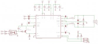
I am also wanting to make this a mono BTL amp. Did you capacitor couple the speaker? The BTL 8ohm circuit on the spec sheet shows the speaker tied directly to the filters, while the stereo version show capacitor coupling. I build a prototype on a solderless breadboard... not the most reliable thing, but I did get it working. It was having problems with the speaker tied directly in, so I tried capacitor coupling it and it started working great! I am not sure if my test speaker is 4 or 8 ohms, so it could be that it's a 4 ohm speaker and thats why it did not work well tied in directly. The speakers I plan to get for the real circuit are all 8 ohms. So I am wondering if the capacitor coupling is needed or not with known 8 ohm speakers.
http://www.diyaudio.com/forums/class-d/196452-class-d-tpa3122d2-single-sided-all-thru-hole-components.html
I want to stick with all thru hole components, since that is what I am familiar with, so I won't be able to get it quite as small as your board, and I would like to stick to single sided if possible, but I'm really curious about your idea of using a double sided board and making the top side one continuous ground plane. If I could implement something like that, I think I could keep it pretty small, even with my thru hole components.
I am wondering how you made the board? it's hard to see the details of the top ground plane with the parts soldered in, I can see where the grounds of the IC are soldered on the top side, but how do you keep the rest of the pins from accidentally shorting to the ground plane? Did you coat the ground plane with something to make it black? or is that just the acid resist you left on it?
I am also wanting to make this a mono BTL amp. Did you capacitor couple the speaker? The BTL 8ohm circuit on the spec sheet shows the speaker tied directly to the filters, while the stereo version show capacitor coupling. I build a prototype on a solderless breadboard... not the most reliable thing, but I did get it working. It was having problems with the speaker tied directly in, so I tried capacitor coupling it and it started working great! I am not sure if my test speaker is 4 or 8 ohms, so it could be that it's a 4 ohm speaker and thats why it did not work well tied in directly. The speakers I plan to get for the real circuit are all 8 ohms. So I am wondering if the capacitor coupling is needed or not with known 8 ohm speakers.
Hi Zaaphod,
For the through-hole components on the ground plane side I simply used a larger drill bit than was used for the holes to remove the copper directly around them. Just don't drill too deep. I think I used the largest size bit that comes in the Dremel drill bit set; maybe second largest.
I didn't use capacitors on the output because I was going for BTL usage. Never had a problem with 4 ohm loads other than the IC running out of current if I tried to push it too hard.
Be aware that using two of these IC's in the same circuit can cause noise problems do to heterodyning effect since the two IC's can't be synced.
Thanks for the info. Sounds easy enough, not much harder than a single sided pcb. Did you coat your top ground plane with something to prevent it from oxidizing?
It could be a power supply problem on my prototype. I was using a 24v 1A switching supply that I happened to have. perhaps my capacitor was just blocking some of the low frequencies so it would work with a limited operating current. I am surprised it even worked on my solderless breadboard with all the leads acting like antennas and questionable connections.
Am I correct in thinking that keeping everything very close together (especially bypass caps) with short fat traces would reduce potential problems?
My idea is to make mono amplified speakers, and run left channel signals to some, and right channel signals to others, these speakers will be a minimum of 3 feet from each other. I plan to keep the wires connecting the speaker to the amp very short, so hopefully I can avoid too many EMI problems.
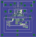
Here's my board so far... I am wondering, with the top layer being a ground plane, should I not have more ground planes on the bottom layer? I don't really need it to be any smaller for any reason, I'm just wondering for performance and noise, if I'm better off with it or without it. any ground plane on the bottom layer. any comments on my circuit board are appreciated.
How did you solder the electrolytic caps to the ground plane? do you just have a short piece of wire feeding through, somewhere then solder them on the bottom? or do you just use the IC pin to also feed thru to the bottom?
How did you solder the electrolytic caps to the ground plane? do you just have a short piece of wire feeding through, somewhere then solder them on the bottom? or do you just use the IC pin to also feed thru to the bottom?
Attachments
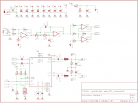
I made new TPA3122D2 BTL boards, this time including a DRV134 to do single to balanced conversion. The DRV134 is running from the same single supply as the amp.
I like to try and use parts I already have if at all possible, so I went a little crazy with 1uF 100V X7R. There are 20 of them per board.
Hi
How did you get running the DRV134 on single supply ?Any schematic or paper reference to read?
I would like to use it too on BTL.
Nice pcb

regards!
ty for reply.
I want to use it on btl as subwoofer amp but I just have single supply :/ (drv134);
by the way in SE mode there's no hmmm or any noise comming out the speaker,stressing the chip it almost got warm. I'm surprised about the power and temperature in a little 20dip package.
Does the BTL mode really give upper 35W ?
My amp working.-->
*I've not done any measure for now
I want to use it on btl as subwoofer amp but I just have single supply :/ (drv134);
by the way in SE mode there's no hmmm or any noise comming out the speaker,stressing the chip it almost got warm
. I'm surprised about the power and temperature in a little 20dip package.Does the BTL mode really give upper 35W ?
My amp working.-->
*I've not done any measure for now
Last edited:
Hi
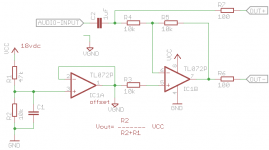
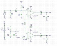
I'm trying to use the amp in btl mode so i need and inverted input and i have not an negative supply,just single supply.
To solve this I was thinking something like the below circuit using VIRTUAL GND and adjusting the offset to input specification of TPA3122
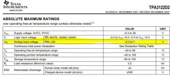
(input = -0.3 to 7vdc )
What do you think?
I'm really confused about the TPA3122 input voltage.

Regards!
I'm trying to use the amp in btl mode so i need and inverted input and i have not an negative supply,just single supply.
To solve this I was thinking something like the below circuit using VIRTUAL GND and adjusting the offset to input specification of TPA3122
(input = -0.3 to 7vdc )
What do you think?
I'm really confused about the TPA3122 input voltage.
Regards!
Attachments
Last edited:
Hi Anonymous I'm having the same problem I'm designing a 2.1 system using TPA3122 but I'll use one chip in BTL for the sub, I will also be using 1 opa4228 for a low-pass and a DRV134 for the input of the BTL tpa3122. My question is how did you manage to use the DRV134 using the same supply as the TPA I'm planing on using virtual grounding with capacitors and resistors, but I don't know what will happen with the virtual ground and the ground of the TPA coul you upload some piece of the schematic ? Thanks
Why just not use simple buffer + phase inverter ?
I chose the drv134 because it needs minimal external components.
Sorry Malquis, I don't normally make schematics.
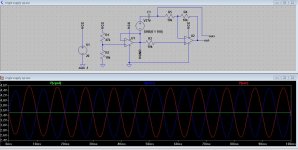
I just loaded a new sim of drv134 on a single supply and now after all this time I see one thing I did really wrong and some component values that could have been optimized.
It's been a long time since I first made this circuit, so I really don't know what I was thinking at the time. I remember having problems with the original sim, but I was also using different software.
I have too many things going on right now, but give me a few days or maybe a week and I will dig these boards out and makes some changes and see it they work any better.
Why just not use simple buffer + phase inverter ?
Hi m-tech ty.
That's what I did at last attempt

The amp is working fine , I'm really glad with this amp config.
regards!
Attachments
- Status
- This old topic is closed. If you want to reopen this topic, contact a moderator using the "Report Post" button.
- Home
- Amplifiers
- Class D
- My TPA3122D2N BTL proto