Hellp Pafi,
In forward mode the circuit behaves like a circuit with a usual MOS Drive. There is no voltage control at all.
- When you want to turn ON the MOSFET, it will be turned with maximum gate source ON voltage (e.g. 10V).
- You turn OFF the FET with minimum gate source OFF voltage (->0V)
And now a design proposal that is valid for every MOS Drive:
- with voltage control in reverse mode
- without voltage control in reverse mode.
The switching slopes could be very much too sharp. For a freewheel FET where you expect high capacitve discharge current in the amp range, it is a must to have a very low ohmic current sink in your MOS Drive Circuit. Otherwise, you will get parasitic effects. The miller capacitor could definitly charge your gate during the transistion from the freewheel to the switching phase! That can lead to driving the FET in linear mode.
When you drive the FET in forward mode, there might be the necessarity to disable this very low ohmic current sink and to discharge the gate with a defined resistor. Then you get a slower di/dt, dv/dt that leads to less noise.
Of course, when you have an antiseriell Diode in the FET path and a parall to to this Diode and the FET, you do not need to consider this miller capacitor charge effect any more. There is no need for a very low ohmic current sink.
Greetings,
Matthias
OK, but my question is: what happens in forward mode?
In forward mode the circuit behaves like a circuit with a usual MOS Drive. There is no voltage control at all.
- When you want to turn ON the MOSFET, it will be turned with maximum gate source ON voltage (e.g. 10V).
- You turn OFF the FET with minimum gate source OFF voltage (->0V)
And now a design proposal that is valid for every MOS Drive:
- with voltage control in reverse mode
- without voltage control in reverse mode.
The switching slopes could be very much too sharp. For a freewheel FET where you expect high capacitve discharge current in the amp range, it is a must to have a very low ohmic current sink in your MOS Drive Circuit. Otherwise, you will get parasitic effects. The miller capacitor could definitly charge your gate during the transistion from the freewheel to the switching phase! That can lead to driving the FET in linear mode.
When you drive the FET in forward mode, there might be the necessarity to disable this very low ohmic current sink and to discharge the gate with a defined resistor. Then you get a slower di/dt, dv/dt that leads to less noise.
Of course, when you have an antiseriell Diode in the FET path and a parall to to this Diode and the FET, you do not need to consider this miller capacitor charge effect any more. There is no need for a very low ohmic current sink.
Greetings,
Matthias
In forward mode the circuit behaves like a circuit with a usual MOS Drive.
Does it? How? What input do you feed to it in order to behave like this, and what determines when do you turn it to this operation mode?
Hello, mias!
Thanks, but again:
Thanks, but again:
what determines when do you turn it to this operation mode?
Hello Pafi,
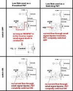
A) When I feed the
- input voltage
- in front of the totem pole stage
- with +5V
then the aparture effects that the MOSFET
- is OFF in forward mode
- is voltage controlled in reverse mode.
B) When I put the
- input voltage
- in front of the totem pole stage
- to GND
I will switch OFF the FET in any case.
Greetings,
Matthias
------------------------------------------------------------------------
Hello Eva,
When you suceed to get such a short transistion time (20nsec), then
- storage charge
- does not have time to bild up
- in case RDSOn * I < 0.6V.
You are trying to minimize the
- dead time between the
- freewheel and the switching phase.
When you can ensure, that you do not come into trouble and there is no risk for a bridge short, then this is fine.
My circuit has a similar effect, but the switch off comand for the freewheel FET comes a little bit earlier than the 20nsec before you give the switch ON command for the switching FET. Therefore you can call my circuit also dead time optimization circuit.
At very high switching speeds
- the stray inductances have the effect,
- that my circuit would switch OFF the freewheel FET immediatly
- when the switching FET is turning ON.
The interaction between
- the stray indances and
- the high di/dt
- will cause huge positive voltages.
In this case my circuit would not effect as a control circuit any longer, but switch OFF the Gate of the freewheel FET very hardly. The only risk you are getting here is, that for some nanoseconds the freewheel diode becomes conductive. But this O.K. because then storage charge does not have time to build up.
You can make the circuit fast,
- by modifying the MOS Drive circuit and
- making the bipolars consuming some standby current of some mA or
- using RF transistors.
The benefit you have is also that the stability of the control is improved.
Greetings,
Matthias
mias!
This is not what I asked.
You are continously explaining the operation of the drawn circuit, but I asked you about what is not on the schematic! The usage / the rest of the circuit / the controll / the timing!
You mean ON, don't you?
But the question was: when you do this (and when you apply the other state)?
("Where is the spade, father?
Next to the rake.
And where is the rake?
Next to the spade.
But where are they?
They are side by side.")
This is not what I asked.
You are continously explaining the operation of the drawn circuit, but I asked you about what is not on the schematic! The usage / the rest of the circuit / the controll / the timing!
B) When I put the
- input voltage
- in front of the totem pole stage
- to GND
I will switch OFF the FET in any case.
You mean ON, don't you?
But the question was: when you do this (and when you apply the other state)?
("Where is the spade, father?
Next to the rake.
And where is the rake?
Next to the spade.
But where are they?
They are side by side.")
Hello Pafi,
Yes, I meant ON. The ON signal is coming in the phases
- where you have current flow in the direction of the body diode and in the phases
- with opposite current direction.
I do not have any sketch of the rest of the circuit. This was just a hobby investigation to understand the reverse recovery effect - not more.
As far as I know - there is no field of application up to now for this circuit up to now. It is not in use yet. Could be, it will become interesting. Especially for audio amplifiers where you have a high PWM frequency, it is worth to minimize the storage charge effects.
Maybe not nowadays, but MOSFETs are getting better and better, and then this circuit maybe quite interesting.
I have one question: How many Ampere are you switching when you use 200V FETs?
Greetings,
Matthias
You mean ON, don't you?
Yes, I meant ON. The ON signal is coming in the phases
- where you have current flow in the direction of the body diode and in the phases
- with opposite current direction.
- I did not check this, but I promise you, there is no problem also when you have a change in the current direction. Here the FET is kept on being switched ON. The proposed MOS Drive circuit even does not realize that because it is only active when you make efforts to switch OFF the Gate. And then only in reverse mode. The circuit is just active for a couple of 100nano secs in the deadtime between the freewheel and the switching phase.In an amplifier this happens in every cycle at idle (and at low signal levels), but you mustn't allow switching off just because the current changes its polarity, FET have to stay ON till the next half-cycle!
I do not have any sketch of the rest of the circuit. This was just a hobby investigation to understand the reverse recovery effect - not more.
As far as I know - there is no field of application up to now for this circuit up to now. It is not in use yet. Could be, it will become interesting. Especially for audio amplifiers where you have a high PWM frequency, it is worth to minimize the storage charge effects.
Maybe not nowadays, but MOSFETs are getting better and better, and then this circuit maybe quite interesting.
I have one question: How many Ampere are you switching when you use 200V FETs?
Greetings,
Matthias
No particular effort is required to get 20ns transitions, they happen when drain current is high and MOSFET capacitances are charged very quickly as a result. If the crossover process is slowed down to, say, 200ns, to allow enough time for the circuit to act, then switching losses increase ten fold resulting in no overall gain.
Your circuit just doesn't have enough time to act. At high currents it should be able to turn on the MOSFET within one nanosecond or so. A "speed-up" capacitor in parallel with the diode could help a bit.
The solution that really works is precise timing of the gate drive signals with minimal drift and overlap.
Have you built and tested prototypes with real components?
Hello Eva,
The waveforms you are seeing are actual real measurements. No simulations or something like that.
The circuit can act pretty fast. All you need is to make the bipolar transistors fast, either with
- taking RF transistors
- or modifying the circuit so, that some mA collector current is flowing through the bipolars. Then they can react very fast.
And this is the best point, you can
- control the MOSFET in
- reverse mode
- with gate source voltage
- below the threshold voltage.
I showed this in the second pic I put in here (05-26-2008 02:24 PM).
This means as soon
- as the current in the freewheel FET
- reverses its direction
- the MOSFET is OFF.")
My circuit does something very similar, believe me, but it just switches OFF the gate of the Freewheel FET, as soon as the the switching FET is switching ON. The time before the gate source voltage is kept to level nearby the threshold voltage.
Greetings,
Matthias
The waveforms you are seeing are actual real measurements. No simulations or something like that.
The circuit can act pretty fast. All you need is to make the bipolar transistors fast, either with
- taking RF transistors
- or modifying the circuit so, that some mA collector current is flowing through the bipolars. Then they can react very fast.
And this is the best point, you can
- control the MOSFET in
- reverse mode
- with gate source voltage
- below the threshold voltage.
I showed this in the second pic I put in here (05-26-2008 02:24 PM).
This means as soon
- as the current in the freewheel FET
- reverses its direction
- the MOSFET is OFF.
The solution that really works is precise timing of the gate drive signals with minimal drift and overlap.
My circuit does something very similar, believe me, but it just switches OFF the gate of the Freewheel FET, as soon as the the switching FET is switching ON. The time before the gate source voltage is kept to level nearby the threshold voltage.
Greetings,
Matthias
- Status
- This old topic is closed. If you want to reopen this topic, contact a moderator using the "Report Post" button.
- Home
- Amplifiers
- Class D
- Disabling MOSFET body diode...