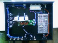
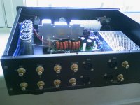
The big white cap is the power reservoir. This is a 47000uF 40V Rifa. Additional caps on the pcb add smaller local storage.
The four caps on the left (with the thin pink wire connecting them to the pcb) are the input coupling caps. These are 7.2uF 630V MKP caps (a pair have just arrived with Davet for testing - see his thread on class-t coupling caps...). Two caps receive the left channel from the pot and two receive the right channel. These four caps then feed the four channels on the pcb, to give L+L+R+R.
This allows bi-amping within one chassis ;-)
wow that looks cool. I made an amp with the sure electronics 4*100w. I'm too getting tired of the white noise. Is the amp9 easy to build, isn't the amp9-basc designed for SMPS?
One question: why do you have such a large power reservoir cap or even one at all? I thought they were only used in linear power supplies to smooth the ripple coming from the rectified current. Think I read somewhere that it is actually a bad thing with a SMPS.
One question: why do you have such a large power reservoir cap or even one at all? I thought they were only used in linear power supplies to smooth the ripple coming from the rectified current. Think I read somewhere that it is actually a bad thing with a SMPS.
sharpi31 said:The big white cap is the power reservoir. This is a 47000uF 40V Rifa. Additional caps on the pcb add smaller local storage.
The four caps on the left (with the thin pink wire connecting them to the pcb) are the input coupling caps. These are 7.2uF 630V MKP caps (a pair have just arrived with Davet for testing - see his thread on class-t coupling caps...). Two caps receive the left channel from the pot and two receive the right channel. These four caps then feed the four channels on the pcb, to give L+L+R+R.
This allows bi-amping within one chassis ;-)
The four caps on the left are nice antennas that will do their best to pick up humm and RF and disturb the amplifier.
Physically big capacitors in the signal path should be avoided, particularly near switching amplifiers and power supplies.
The big supply capacitor is ok as long as the control loop of the switching supply does not become disturbed.
The 4 coupling caps are shielded and grounded to the chassis - won't this minimize the the interference pickup? I assumed this would be ok, but could be wrong...
How would I know if the control loop of the smps was effected by the large PSU cap (what could I measure to check this)?
Thanks for the feedback.
How would I know if the control loop of the smps was effected by the large PSU cap (what could I measure to check this)?
Thanks for the feedback.
Col,
The smps is a 108W 24V unit. See this link for more info...
SMPS info
I picked it as it was cheap and has a fixed 83KHz switching frequency (which is higher and further from the audio band than many others I looked at).
The amp9 is pretty easy to build - winding the inductors takes longer than anything else. Soldering the 16 diodes is tricky, but not too bad if you use a cocktail stick to apply a tiny blob of super-glue under each one. Once they are held in place soldering becomes much easier. Don't use more than a tiny blob or the glue will spread and cover the pcb pads when you site each diode.
Big PSU caps help remove the ripple from linear supplies, but also act as storage for when the amp requires current very quickly. While there isn't the same ripple with an smps, you still need caps to supply power quickly.
Thanks for that info on the amp9 kit. I'm tempted to have a go at an amp9-basic. Will hold off for a bit though as I'm currently building 2 amps based on the Hypex UcD180 and that is keeping me entertained.
I managed to pick up 4 Lambda JWS300 a while back and have put 2 up for grabs on ebay, they will be the perfect power source for a amp9. There is also a post here: http://www.diyaudio.com/forums/showthread.php?s=&threadid=121855
Will keep the other 2 and maybe have a go at a nice Lambda/41hz amp9 in a couple of months.
BTW I think there is a few of us about to embark on an attempt to reduce the white noise in the sure electronics 4*100w, you might want to keep an eye on that thread.
")
I managed to pick up 4 Lambda JWS300 a while back and have put 2 up for grabs on ebay, they will be the perfect power source for a amp9. There is also a post here: http://www.diyaudio.com/forums/showthread.php?s=&threadid=121855
Will keep the other 2 and maybe have a go at a nice Lambda/41hz amp9 in a couple of months.
BTW I think there is a few of us about to embark on an attempt to reduce the white noise in the sure electronics 4*100w, you might want to keep an eye on that thread.
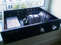
I bought the case from a seller on Ebay...
DIY Gene
I like soldering but am useless at constructing cases, so I've bought the DIY Gene A28 case for the last two amps I've built. They are superb for the money (10mm thick fascia!).
That's why my four speakon connectors are sitting in holes marked 'balanced' - the speakon sockets are the same fitting as neutrik XLR chassis sockets.
I admire others with the skill and inclination to build their own cases. Me, I'd rather buy something like this and spend my time and effort on the bits on the inside.
Beautiful AMP9
Excellent, chassis and amplifier. Thanks, for the link for the chassis. I have a number of T-amps in various stages of breadboarding. This chassis looks like it maybe just the solution.
After seeing your handiwork on the AMP9 I am really looking forward to testing the caps you sent me.
Excellent, chassis and amplifier. Thanks, for the link for the chassis. I have a number of T-amps in various stages of breadboarding. This chassis looks like it maybe just the solution.
After seeing your handiwork on the AMP9 I am really looking forward to testing the caps you sent me.
- Status
- This old topic is closed. If you want to reopen this topic, contact a moderator using the "Report Post" button.
- Home
- Amplifiers
- Class D
- Amp9 with SMPS (my first class-d)