Ok, well, they don't teach us jack' about how to actually design stuff in college.
Short story: building UCD amp, AL+steel chassis.
Amp is going to have two modes:
-1st mode: audio pre-amp/processing using TDA7439 IC, unbalanced
-2nd mode: direct connection to XLR balanced inputs, "bypass mode"
Obviously the chassis GND will be connected to AC GND, that's a given.
My questions are (for best audio performance):
Should there be some sort of connection between circuit GND and AC GND, or should the circuit GND remain isolated from AC GND?
What should pin 1 of the XLR connector be connected to, if circuit GND is not connected to AC GND?
How should I connect the TDA7439 to the UCD module input? Ground the inverting input to the pre-amp circuit GND and connect the output from TDA7439 to the non-inverting input?
Should the amp circuit GND be tied to the pre-amp circuit GND?
I want to avoid powering this thing on and getting nothing but HUUUUUUUUUMM.
TheMG said:Should there be some sort of connection between circuit GND and AC GND, or should the circuit GND remain isolated from AC GND?
[/B]
'Chassis ground', 'power ground' and 'signal ground' are all seperate concepts. They must all be connected, but in a specific way.
In short, the signal ground must remain unpolluted by currents from either the power supply or chassis. There also must not be any loops in the signal ground. Remember that every wire is not a perfect conductor-- As long as you avoid loops in the signal ground, and avoid eddy currents in the chassis or ripples in the PSU from sharing the signal path *at any point*, you've done it right. That includes avoiding loops through the chassis (eg, if you insist on allowing an unbalanced input, do not use a connector that grounds to the chassis; you will have a signal ground loop throught he chassis that way).
If you want an example, look up the kit at chipamp.com, and look at how the grounds connect on the PC board. It is a good example. Yes, I realize that's a class AB, but it's still instructive
")
TheMG said:What should pin 1 of the XLR connector be connected to, if circuit GND is not connected to AC GND?
[/B]
Pin 1 connects to the chassis at the closest possible point inside the case. The shield ground on a balanced cable is always a chassis ground unless a manufacturer screws up.
Shields are shielding against magnetic and capacitive coupling, and as such they're designed to suck in and carry away noise currents. These noise currents must not conducted to a signal ground.
Signal ground is only for signals.
TheMG said:Should the amp circuit GND be tied to the pre-amp circuit GND?
[/B]
All signal grounds must be connected together, preferrably at a single point. Avoid any loops (cycles in the ground graph).
I only want to complement xiphmont's excellent reply.
Be sure that all the grounds are connected to the chassis at a single point.
And you are right, they don't teach this at college.
One of the very first projects I did fresh out of college was install a school intercom system. The system had three powered master stations and several slaves. Well, stupid me, I installed the power supply at one of the master stations and used the same signal return wire as the power return wire for the rest....you can imagine the ensuing hum and motorboating!
But I did learn the lesson.
Ok, am I getting this right? I hope the diagram is not too confusing, just hacked that together in a few minutes.
The relay is really just a bypass. The goal is for the amp to be usable for home use without an external pre/processor , but to also be usable for PA use or in the future or with a more sophisticated source unit. Also to be able to compare SQ with and without the TDA chip.
The relay is really just a bypass. The goal is for the amp to be usable for home use without an external pre/processor , but to also be usable for PA use or in the future or with a more sophisticated source unit. Also to be able to compare SQ with and without the TDA chip.
Attachments
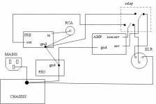
TheMG said:Ok, am I getting this right? I hope the diagram is not too confusing, just hacked that together in a few minutes.
That's basically right. You have two 'stars' (the XLR ground is going to the preamp not the star ground, so you could end up coupling the return path from the XLR into the ground reference) but there are no loops. That won't hum and the THD increase, if any, would almost certainly not be noticable. I've certainly done it that way myself.
Oh, and chassis grounds are usually not starred. They're removed from the signal path and do whatever. It's usually best to tie chassis grounds close to where they're 'coming from'.
xiphmont said:
the XLR ground is going to the preamp not the star ground, so you could end up coupling the return path from the XLR into the ground reference
The XLR return path never goes to the pre-amp, it either goes to the inverting input of the UCD module, or nothing at all.
Basically, the relay completely bypasses the pre-amp/processor circuit and couples the UCD modules directly to the balanced XLR inputs.
xiphmont said:Oh, and chassis grounds are usually not starred. They're removed from the signal path and do whatever. It's usually best to tie chassis grounds close to where they're 'coming from'.
That's actually what I was going to do at first, for the IEC power connector and XLR connectors I was gonna use a very short length of wire with a lug and tie it to one of the nuts holding the connector in place on the chassis. For the PS, same idea, connected to one of the screws holding the PCB in place.
The RCA connectors I have purchased are insulated from the chassis, so that turns out perfect.
Thanks for the replies.
- Status
- This old topic is closed. If you want to reopen this topic, contact a moderator using the "Report Post" button.