1.After playing with different input configurations for self-oscillating class D I would like to get your opinion and facts on difference between having Comparator (LM311) on input of amplifier versus High speed OPAMP (LM6132,LT1220)...What is a difference?Which one is better?
2. I have seen that some design's (IR design,...) are using feedback prior to output coil.Some other use after output inductor.What is a main difference and which one is recommended?
Most of the amps with OPAMP on input are using FB prior to output inductor.WHY? Can it be modified so FB is taken after(if is better)?
Regards....
The IR reference designs all use pre-filter feedback. Post -filter feedback requires a different amplifier architecture, although to an unpractised eye, the pre and post-filter self-oscillating designs look very similar. You can build a post-filter (UCD style) amplifier using the IRS20124 or IRF20955 chips, but the recent IRS2092 with the modulator included in the driver chip can't be used for a UCD style of amplifier.
To get an understanding of the UCD amplifier with post-filter NFB, try to find an on-line copy of Bruno Putzeys AES paper. (I don't have a link for this but I'm sure someone else here has).
The modulator stage really needs to be a high-speed comparator. The LM311 or LM319 will work, but something like an LM361 is better if your MOSFET driver stage will accept TTL-level inputs. Even high-speed op-amps don't make good comparators.
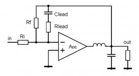
It might not be that simple. If you look at the latest IR reference design (IRAUDAMP5), you'll see it uses the IRS2092. The 2092 has an input stage which is basically an op-amp, followed by a separate comparator. The two together form the modulator, as in a sigma-delta amp (like this one), the comparator works on the combined signal from the op-amp. The op-amp isn't doing the switching, simply merging the input and feedback signals and applying the required frequency compensation.
In a UCD-style amp, the comparator has one input from the incoming audio, another from the NFB network, and simply switches (with no hysteresis required) when one input to the comparator passes the voltage on the other. This switching needs to be as fast as possible.
So basically you need to see in a particular design where the transition between the linear signal and the PWM signal is happening. This stage always requires to be a comparator of some form. Although an op-amp will work happily as a comparator at low speed, at higher speeds the output is unlikely to slew fast enough, and if you run an op-amp open-loop, it is also likely to have a noticable delay when coming out of saturation. As you will want to be switching in the 300 to 400kHz region for a full-bandwidth class-D amp, then I would have thought that an LM311 is about the slowest device you would think of using.
How about inverting UCD with IRS2092?, but the recent IRS2092 with the modulator included in the driver chip can't be used for a UCD style of amplifier.
Attachments
lumanauw said:
How about inverting UCD with IRS2092?
It might be possible. The input op-amp is a transconductance amplifier (OTA), so the link between the - input of the comparator and the output of the OTA is at a high impedance. You possibly could insert the post-filter NFB signal in at this node using a suitable network. It would be easy to model the input OTA using normal SPICE building blocks so I might have a go at seeing if I can get a similar architecture to work properly.
Checking the 2092 data sheet shows that the input OTA has a transconductance of 100mA/V. You can't put NFB locally around this stage as it would then make the OTA into a voltage amplifier, which would have a low output impedance, requiring a resistor to be inserted between the amplifer output and the comparator (which is not possible).
It might be possible to ignore the input OTA altogether (by connecting both its inputs to 0V). It will then not be trying to source or sink current to/from the input of the comparator, allowing a normal inverting UCD style connection to the comparator (as you show in your diagram).
I've got some DIL IRS2092 samples, but no time at the moment to try this out unfortunately.
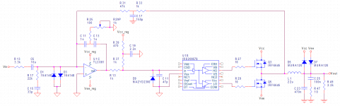
It's been six years but, other than the IRS20957S replacing the IRS20955, not much has changed. IRAUDAMP5 is now one of IRF's older reference designs but it still has the second best headline THD+N figures in the current lineup. It's bested by IRAUDAMP4A, which is the IRS20957S reference design, though the IRS20124 remains in production and its reference design---IRAUDAMP3---is only slightly lower performance.
The class D portion of IRAUDAMP4A manages about -102dB THD and -91dBV noise in single channel driven (figure 21 in the reference design datasheet linked above) so it's the CS3310 volume control on its input which limits headline performance. This compares well with Hypex nCore's -110dB THD and -93dBV noise and other high performance class D implementations such as DDFA and NCDX. This makes the 4A reference design an interesting starting point for DIY, either directly or for UcD type implementations. The schematics in its datasheet are a bit scattered and little hard to follow. So I decided to draw the attached, which simply omits components off the self oscillating signal path and groups everything together for readability. Given the quietness of this thread there's likely not many folks interested in it being bumped. But I opted to share the result anyway. Screenshot+upload is quick and IRAUDAMP3 uses essentially the same circuit, so the details are of interest for 20124 implementations as well.
What this shows is IRF gets nearly best in class headline performance out of a fairly basic op amp repurposed as a comparator---Mouser has the TLC081 for USD 1.57---and pre-filter feedback. One would have to measure the TLC081 and perhaps have a look at TI's Spice models of it to see if it exhibits rail stickiness. It may be the input clamp diodes---D1 and D3---mitigate some of the error mechanisms Analog discusses in this app note on using op amps as comparators. If Bruno Putzeys (Hypex's lead designer) were on this thread I imagine he'd point out the linearity limitations imposed by the lack post-inductor feedback, which is fair enough. Section 1.1 of Bruno's UcD paper also happens to note some of the limitations of the hysteresis switching topology IRF uses.
Bruno's follow up paper points out class D loop gains are modest at second order and modulator linearity tends to be more effective in providing amplifier performance. I may find further enlightenment in my reading of the datasheets but what they're suggesting me is the TLC081+IRS20957 combination is about as linear as the discrete comparator and level shifter employed in the nCore amplifiers, perhaps somewhat moreso. Since ICs offer better matching than discretes this isn't exactly a fair comparison. The TLC081is also unusual in that it's falling slew rate is somewhat higher than its rising rate, so it's possible some error cancellation may occur between the TLC081 and IRS20957. But this may suggest some of the emphasis on high speed comparators one here on the class D forum (such as say, this worthy thread) might be misplaced.
As I look at the possibility of swapping out the TLC081 for something else it seems clear the TLC081 is not all broken in this application. This suggests one should be careful about fixing it as there are reasonable odds fixes might result in worse performance. This is not to dispute the concerns about op amp switching performance but as I look through parts selectors at Analog, Maxim, TI, and so on one thing I note is suitable comparators most all have uA bias currents rather than the pA biases of FET input op amps like the TLC081. On an initial look it seems plausible comparator bias could result in lower modulator linearity than op amp switching limitations. A twist in this case is IRF has the TLC081 wired up to swing to about -4.75V and relies on D9 to clamp that to max spec on the IRS20957's input pin of -0.3V. At the TLC081's typ rising and falling slew rates this would cause rising edges to come in around 50ns late, though I'd have to do sims to see how much mitigation is provided by the R37+R39 pull up and the three separate RC lowpasses on the TLC081's output.
The other area where I find myself hesitant is noise. Most comparators aren't speced for noise but parts designed for speed usually have higher 1/f corners and higher noise floors. With BJT based parts, such as most comparators, current noise dominates when impedances rise above a few kohm, resulting in lower noise from FETs. Since class D signal gain, noise gain, and loop gain all track together and the THD+N performance of the amps mentioned in this post is noise limited some caution seems warranted. A low offset, low noise, and likely slow FET op amp might be more accurate in placing edges in time than a fast comparator and could therefore form a more linear modulator. Curiously, while the TLC081 supports offset null the pins aren't hooked up in IRF's schematics. Design oversight? Tried but found unnecessary? I don't know, but the TLC081 is pretty good on offset and noise---the OPA134 is comparable but the LME49880, OPA1641, OPA1652, TL072, and such are all worse. There are several FET op amp options which one try, the ADA4898 is perhaps one of the more interesting ones.
A natural way of answering these sorts of questions would be to pick a couple op amps and couple comparators and lay out a board which could accommodate any of them in, say, 8-SOIC. If anyone's done this I've not turned up the data, though. Sims would also offer insight. But a fair bit of model validation would be required and, for small residuals like a few uV of noise or THD below -100dB, it's hard to get trustworthy results.
Attachments
")
What about them? It's unclear what question you're asking which wouldn't be answered by the datasheets and perhaps a text such as Walt Jung's op amp applications handbook. If you're looking for a offset frame of reference a 100pA bias shift with a 10k source impedance results in a -100dB error on an amplifier with 20dB gain outputting 1V. This is below the noise floor of the amps I mention in post 8, but not by so many dB as to be negligible, and is comparable to their THD. It's plausible a bias shift on this order of magnitude could occur when combining pre-filter feedback with BJT implementations with good bias compensation such as the two parts you mention. It's rather less likely with post-filter feedback as the carrier attenuation means the control device in the loop sees less variation in its operating point. Bias details are usually only present in low bias current op amps' datasheets so it's a question best answered by measurement.
With regards to comparators the UcD paper provides the schematic used and some basic performance figures. The nCore white paper provides some hints as to the improvements made (see links above). Few integrated comparators exceed the switching performance of the UcD implementation. The most interesting part from Maxim is probably the MAX998, which happens to have one of the lower bias currents among Maxim's fast comparators. Its datasheet contains some bias characterization and suggests it would shift by hundreds of pA when used with pre-filter feedback. I don't know which transistors Hypex uses on the UcD modules but as it's an uncompensated design I would tend to guess uA to hundreds of nA bias. Since it spans the full supply rail to rail voltage it's probably less susceptible to operating point shifts. Also, unlike IRFs designs, UcD source impedances are matched so the offsets will tend to track. This could probably be simmed with reasonable accuracy. From TI the most interesting offerings I'm seeing are the LMV761, TLV3201, and TLV3501, all of which happen to be FET input.
The order of the modulator is a consideration along with the location of the feedback tap. Higher order modulators have more integrators and the corresponding increase in lowpassing provides additional carrier attenuation and operating point stabilization. IRAUDAMP3 and 4A are second order, UcD is first order but the post-filter feedback yields third order lowpass to the comparator inputs. I can't say I'm entirely certain as to how to think about this but a basic rule of thumb which might be reasonable is that for each additional order an order of magnitude increase in bias currents is acceptable.
It's rare discrete circuits can compete with integrated ones for performance. But, given the supply restrictions of fast comparator chips, I'm tempted to approach this as a discrete comparator versus fast integrated op amp kind of design question. I took a look at some UcD transient sims in TINA-TI and found model grief. IRF provides current DirectFET models but offers only old gate driver models, all of which seem to require COM be ground rather than Vee. The gate driver will drive and the control device self oscillate, but the TI op amp models I've tried don't seem to support single supply. So there doesn't seem to be a simulation configuration where both models can work at the same time. Issues with models relying on internal connections to node 0 are unfortunately normal. I haven't checked every TI and IRF model of interest so, while there might an exception to the norm, if one wants to run sims probably the best options are 1) look at just control device switching behaviour on its own or 2) set up the sim with a gate driver implementation which doesn't rely on node 0. The DirectFET models I've looked at also reference node 0, so there may be issues there too.
If you were asking about THD+N from noise induced jitter, well, that's a separate post.
Bumping this thread again for new findings. Jun Honda says the IRS2092 supports arbitrary combinations of pre and post-filter feedback in the Customizing Feedback Loop section of Differentiating Cost-Competitive Class D Amplifier Designs. I'm not finding anything more from IRF on this but there's February 2014 discussion of an IRS2092 UcD implementation on this DIYA thread.How about inverting UCD with IRS2092?
- Status
- This old topic is closed. If you want to reopen this topic, contact a moderator using the "Report Post" button.
- Home
- Amplifiers
- Class D
- Input Comparator VS.OpAmp and FB type