Hi All,
I have quite finished the design of a 12V powered class-D amplifier using the new chip from International Rectifier called
IRS2092.
The amplifier can be used in BTL mode delivering up to 500W into a 4ohm load (I hope....).
By now only the power supply has been mounted showing good
performances. The amplifier section is not yet assembled, so I cannot tell you anything about it.
I know that the schematics is still full of little mistakes and some
components values has been changed.
Please take a look at it and tell me what do you think.
Attachments
Hi all,
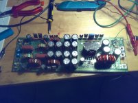
I have finished assembling my car amplifier. Everithing looks promising but I haven't done any power test yet.
The mosfets remain cool even without heatsink and the waveforms on the SMPS transformer and on the amplifier switching node look perfectly square without any appreciable ringing.
Now the power supply PWM frequency is set to 120kHz and the class-D frequency is set to 380kHz and the amplifier is powered
at +/- 50V
The power supply seems to work without problem but the
amplifier output inductance gets very hot even at idle after few
minutes.
I suspect that core losses are too high since the same behaviour appears even at idle.
The output filter is a 4th order bessel type with 35kHz corner frequency with 2ohms load. I have calculated the ripple current on the first inductor and it is around +/- 1A so I suppose that the losses are not due to the wire gauge.
I have tried to rewind the inductance using home made litz wire but basically nothing changes... it still remains very hot.
The inductor I used is the Bourns 2300-HT-220-RC rated for 19A of continuous current and 8mohms of DC resistance.
I have measured the inductance value and it has the right value (22uH). It has 17 windings so the AL value of the core must be 76nH/t.
Can you recommend me an inductance or even a ferrite core that can be used at those frequencies and at those power level?
Thank you
Attachments
 You do the SMD soldering by hand? How does it perform, sonically?
It seems that you are developing a commercial product.
Did you make any core loss calculations? The selection of iron-powder materials suitable for class D is quite limited. You can find useful resources at www.micrometals.com
Consider the following changes:
- Use a toroid transformer in the SMPS for reduced leakage flux.
- Remove the big electrolytics before the 12V input filter inductor or they will overheat and vent. This is because they will be subject to extreme ripple currents (alternator and vehicle PWM) when the amplifier is placed in a vehicle. Use film and small high ESR electrolytics only.
- Use the on voltage drop across the primary side SMPS MOSFETs to trigger the overcurrent condition. You don't need a separate sense resistor.
- Change the "remote" scheme to avoid drawing 1mA when the amplifier is off.
- Separate primary and secondary side grounds. Use optocouplers to transfer signals.
- Consider implementing the protection features with a small microcontroller. It saves plenty of parts.
BTW: You have an input preamplifier and filtering stage, don't you?
Thank you Workhorse,
so you think also that is the core that have high losses
at this frequency.
I see on the specs of the T106-2 core that the AL value is only 13.5. To reach 22uH I need 40 turns on that core so I can not use
a very thick wire.
Which wire diameter do you suggest knowing that the output
load will be 2ohms. Is a litz wire necessary or I can use a solid wire?
To assembly the SMDs I use solder paste and an hot air blower.
The smallest components on my amp are 0603 but with this technique you can even mount smaller components such 0402 or even 0201. Basically is the same technique used in mass production, the only difference is that you need to manually put the solder paste on the components pads, manually position the components on the right place and finally heat everything up until all the soldering are done.
Eva said:It seems that you are developing a commercial product.
Did you make any core loss calculations? The selection of iron-powder materials suitable for class D is quite limited. You can find useful resources at www.micrometals.com
Consider the following changes:
- Use a toroid transformer in the SMPS for reduced leakage flux.
- Remove the big electrolytics before the 12V input filter inductor or they will overheat and vent. This is because they will be subject to extreme ripple currents (alternator and vehicle PWM) when the amplifier is placed in a vehicle. Use film and small high ESR electrolytics only.
- Use the on voltage drop across the primary side SMPS MOSFETs to trigger the overcurrent condition. You don't need a separate sense resistor.
Thank you Eva,
no it not a commercial product at all... it is just for fun and it is my first class-D amplifier desing. I have made it with SMD just because I think that they are much more easy to handle rather than standard components.
The SMPS transformer core is Epcos RM14 with N87 material. It can handle around 1kW at 100kHz; beeing a closed core I don't think that the radiated EMI will be a concern. I used an RM core just because it was readily available and it is much more easy to mount on a PCB. In any case I will try with a toroid and see what happens.
I will remove the first electrolytic to avoid problems. It was only to improve filtering but of course the ripple current will be huge...
You mean using the Rds-on of the mosfet for current sense? Nice idea, I like it. In any case the current protection does not work now, There is some noise picked up from the trace connecting the
sense resistor to the SG3526 that makes the protection tripping even at idle...
Ouch... If you are not experienced you are going to have a hard time making this current limiting (and the entire project) work. Consider leading-edge blanking and low-pass filtering to cancel shunt inductance, and don't underestimate the EMI radiating cpabilities of such a push-pull transformer, it's leakage inductance what causes trouble... Foil windings and a flux band may help, but it's just easier to use a toroid. Remember that you will need slope compensation for current limiting with duty cycles above 50%.
Another recommendation is to use fast recovery rectifiers rated at the lowest possible voltage because they have lower Qrr resulting in a smaller and shorter turn-on current spike at the primary side (and less EMI radiated by the transformer).
Another recommendation is to use fast recovery rectifiers rated at the lowest possible voltage because they have lower Qrr resulting in a smaller and shorter turn-on current spike at the primary side (and less EMI radiated by the transformer).
I have added a 100nF cap in parallel to the current sense shunt and I have replaced the capacitor in parallel with the SG3526 current sense input pin with a 1uF cap (it was 10nF). Now the current limit protection does not trip anymore at idle but I don't know if it trips when needed....
I think that a 1uF capacitor will slow down the overcurrent protection making it almost useless.
For the diodes I use the RURP3060 from Fairchild rated 30A 600V.
No indication about QRR, in the datasheet only trr is shown and it is 55ns.
There is also another version of this diode called RHRP3060, same voltage and current ratings but faster, 40ns.
I have found another issue with the SMPS: when the input voltage reaches 14.8V and the output is regulated to 48V it start
to work in discontinuous mode. If I open the feedback loop the dutycycle comes back to around 50% and the output voltage is 60V.
Can the SMPS work in discontinuous mode at idle or there are some drawbacks in doing it?
Probably removing one turn from the transformer secondary side will solve the issue, what do you think about?
I think that the most elegant way to solve this problem is to use syncronous rectification but it involves a complete redesign of the power supply and I want to avoid it.
Ouch!!
Aren't you doing any math/physics to figure out optimum component values?
 I become quite puzzled when I see people replacing 10nF by 1uF and asking if it won't be "too slow". There are optimum values that give best parasitistics cancellation and noise rejection with little sensitivity loss, but you have to calculate them or find out the ones producing best waveforms with oscilloscope.
Discontinuous operation is harmless, it actually results in less EMI.
I would just use 200V diodes. Qrr may be 3 o 4 times lower. The RHRP is the hyper-fast version, I think, while the RURP is the ultra-fast.
Have you considered the implications of using two separate filter inductors for SMPS regulation? You should have used a single coupled one.
Aren't you doing any math/physics to figure out optimum component values?
I become quite puzzled when I see people replacing 10nF by 1uF and asking if it won't be "too slow". There are optimum values that give best parasitistics cancellation and noise rejection with little sensitivity loss, but you have to calculate them or find out the ones producing best waveforms with oscilloscope.Discontinuous operation is harmless, it actually results in less EMI.
I would just use 200V diodes. Qrr may be 3 o 4 times lower. The RHRP is the hyper-fast version, I think, while the RURP is the ultra-fast.
Have you considered the implications of using two separate filter inductors for SMPS regulation? You should have used a single coupled one.
Ok it was just a quick try... The only capacitors that I have now in 0603 package are 1nF, 10nF and 1uF so let's try with one of these. For sure I will do some calculations/simulations to find out the best value
I have used two separate inductances mainly to simplify the PCB layout.
What are the benefits of using one common core for both positive and negative rail?
I have used two separate inductances mainly to simplify the PCB layout.
What are the benefits of using one common core for both positive and negative rail?
When current draw is not equal in both rails, one inductor may be working in discontinuous mode and the other in continuous mode. In these circumstances, the voltage in the discontinuous mode rail will tend to be pumped to the maximum unregulated value. If the discontinuous side is the only being sensed, then the voltage in the continuous mode side will drop instead. Your current design should only be used in bridge mode. The coupled inductor avoids these problems almost completely.
Hi Eva,
I am still trying to make this current limit protection work, and it is not an easy task.
I have made some simulations and seems that even a 5nH series inductance in series with the shunt resistor creates very huge voltage spikes between the mosfet sources and gnd. I think that a TO247 package has at least 10nH of parasitic inductance so the situation is even worse.
I have noticed that after some minutes at idle the shunt resistor becomes hot. How is it possible? it is a 2mohms and the parasitic inductance can not heat up... The idle current consumption on the primary side is 1.27A.
The shunt part number is Riedon FPR 2-T218, it is rated 2W without heatsink and 30W with heatsink.
thank you
Hi Eva,
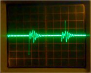
this is the waveform I see accross the resistor terminal at idle
The scale is 1V/div - 1us/div
there is an oscillation of around 4-5MHz. Can it be caused by the shunt inductance + some parasitic capacitance? In any case I think that the main problem are the spikes as high as 2.5V.
I have tried to put a capacitor in parallel to the shunt but the situation does not change too much.
The frequency is set to 110kHz (oscillator running at 220KHz)
I will try some more test an I let you know
Attachments
Leakage inductance of current measurement shunts introduces a zero at F=R/(2*pi*L). This effect is cancelled by adding a pole at the same frequency. An RC lowpass does the trick, F=1/(2*pi*R*C).
Ringing is another story. It comes from LRC resonators made out of circuit parasitistics. A TO-247 may easily exhibit 20nH total parasitistic L, while 12nH is the typical figure for a TO-220 with short leads. Then it comes PCB trace inductance. Transformers are evil because they exhibit complex parasitistics due to capacitance between turns of different windings, non contiguous turns of the same wnding and distributed leakage inductances.
Spikes may be a sign of cross-conduction or too fast hard switching. They appear bigger than real due to the zero in the unfiltered shunt frequency response. They also cause energy to be sotred in parasitistic RLC tanks and to be progressively released during a long period of time resulting in ringing.
Leading edge blanking allows to get rid of spikes. Consider keeping current limit inactive during the first, say, 500ns of the cycle.
Thank you,
so with the values involved a 1uF capacitor in place of C109 will create a pole that cancels out the zero created by the shunt.
I think also I have some cross conduction problems. If I look at the mosfet drain waveforms I see that they can potentially overlap. I can not see it clearly on my scope because of the very very reduced bandwidth (it is 40 years old an 2MHz BW....)
In case crossconduction occurs increasing the dead time may help.
I don't see any strange current consumption peaks due to cross conduction but by now I am using a 3A current limited power supply. I have not yet connected a car battery instead of the power supply to avoid to blow everything up just because of stupid mistakes...
I will try with the 1uF cap and let you know
I have tried with 1uF and the spikes after the low pass filter are now around 20mV. It seems to be ok but what about the speed of the current sense circuit?
The crossconduction problem seems to be quite confirmed. The mosfet starts to heat up after about 10 minutes (no heatsink).
I will try to increase the dead time
The crossconduction problem seems to be quite confirmed. The mosfet starts to heat up after about 10 minutes (no heatsink).
I will try to increase the dead time
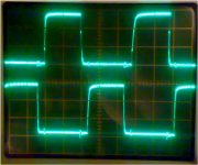
I have tried increasing the dead time but the results is always the same.
Now I have around 400ns of dead time but the results are basically the same as before.
The shunt and the mosfets still heat up at idle (with no heatsink).
Attached you will find the gate waveforms, it seems that the gates are driven very fast and with a good sqarewave.
BTW: I am using the UCC37322 as gate driver IC. This IC can sink or source up to 9A peak. The mosfets have 300nC QG (one pair of 150nC each).
Attachments
- Status
- This old topic is closed. If you want to reopen this topic, contact a moderator using the "Report Post" button.
- Home
- Amplifiers
- Class D
- Class-D Amp with IRS2092