Probably I have found the root cause of the mosfets heat up.
The huge gate to source capacitance of the IRFB4110 (about 10nF each device) creates a very high current peak trough the shunt when the gate is charged. My gate driver is rated 9A and I have a 3.3ohm series resistor to the gates.
I have tried to increase the value that resistor up to 10ohms, the voltage spikes on the shunt reduces from about 2V to 0.9V.
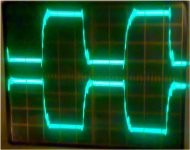
I have even tried to replace these mosfets with the IRFZ24N (I know that it is not enough for this application but I have only this part available now). The IRFZ24N has a gate capacitance of about 370pF and the voltage spikes are even more reduced. The gain and drain waveforms are much better now with the IRFZ24N.
Do you think I should change the SMPS mosfets?
The same mosfet I use for the class-D can do the job (IRFB4227)
thank you
The huge gate to source capacitance of the IRFB4110 (about 10nF each device) creates a very high current peak trough the shunt when the gate is charged. My gate driver is rated 9A and I have a 3.3ohm series resistor to the gates.
I have tried to increase the value that resistor up to 10ohms, the voltage spikes on the shunt reduces from about 2V to 0.9V.
I have even tried to replace these mosfets with the IRFZ24N (I know that it is not enough for this application but I have only this part available now). The IRFZ24N has a gate capacitance of about 370pF and the voltage spikes are even more reduced. The gain and drain waveforms are much better now with the IRFZ24N.
Do you think I should change the SMPS mosfets?
The same mosfet I use for the class-D can do the job (IRFB4227)
thank you
Ouch! You have still a lot to learn.
The 1uF capacitor directly in parallel with the shunt is a completely crazy idea as a means to compensate inductance. I told you to use a RC filter. What do you get if you place R and L in parallel???
A 9A gate driver is also a crazy idea for your application. The gates have to be charged much slower than that. You could even drive them directly from a SG3525 with cleverly used ferrite beads.
Go back to the IRFB4110 and find a reasonable gate drive speed and dead time.
You are going to need an oscilloscope with at least 40Mhz bandwidth and digital storage mode comes very handy too.
Next time you take oscilloscope pictures, adjust the image to show the edges of the waveforms because nothing interesting happens during the flat portions.
No the 1uF is not in parallel with the shunt.
There is a low pass filter with R=12ohm and C=1uF (see attached schematics). The other 22ohm resistor is used as a voltage divider. The current limits trips on on the SG3526 when the voltage is > 100mV. I can not use higher values resistor because the input of the SG3526 is intended for a low impedance load (<50ohms). The R=12ohm and C=1uF create a pole at 13.2kHz, more or less the same frequency of the shunt zero (15.9kHz for 20nH and 0.002ohm).
Probably this week I can access to a 100MHz BW oscilloscope at my job. I will try to capture the waveform with that scope.
Do you think that the SG3526 outputs are strong enough to drive two IRFB4110 fast enough at 110kHz? (the Qg is 150nC).
I will try to remove the driver and see what happens. For the ferrite bead you mean using it in place of the gate resistor?
Is it used just to avoid possible oscillations of the mosfet or it has some other purposes too?
The dead time you see in the waveforms is huge, I know this. It was just to be sure that no cross-conduction appears
thank you
Attachments
Then the LPF is OK.
Concerning the gate drive, leave the 9A ICs in use but add a diode in parallel with a resistor in series with the existing gate resistors so that you can set independent turn-on and turn-off "speeds".
3.3 ohms is probably producing a way too fast turn-on and a barely fast enough turn-off, 10 to 50 ohms may improve things a lot, but keeping the 3.3 ohms for turn off. Try to aim for cross-over times in the 100ns to 200ns range.
Ferrite beads as gate drive "ballasts" have a series of unique advantages. You may want to use the search engine of the forum to find and read my comments on them. Anyway, the best way to learn about them is to try them in various sizes and study the resulting waveforms.
")
mag said:4148? with only 100mA average current and 500mA peak I think it will blow up with such current...
I will search for a fast diode rated at least 1A continuous
Ok, you choose, but bear in mind, that junction will damaged if Tj>150C or around. 500mA as peak forward current pointed for the specific case, probably for 1 of 50hz semiwave, for your case 4148 shouldn't be so hot, because average current will much lower 100mA, especially due to 10Ohm output impedance of the irs2092. BTW, what is the reason for using this diode at all? 2092 has dead time setting already, or 100nS is too fast for you?
I think I made it!
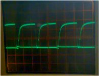
I have used 22ohms for charge and 3.3 for discharge (trough diode). I have used a schottky diode BAT42.
Then I have set the dead time to around 500ns.
Now the mosfets are running perfectly cold and also the spikes trough the shunt are reduced (less than 0.8V)
In attached there is the gate waveform (2us/div).
Not the only issue I see (I hope) is the output class D inductor that becomes hot. I have ordered some MPP cores but I am still waiting for the delivery... As sone as I get some news I will let you know.
Thank you all
Attachments
BAT42 is rated 200mA continuous and 4A peak. Probably also a 1n4148 will work also, but I don't like this diode in this application.
In any case it is just a try; BAT42 is a trough hole diode and I need an equivalent in SMD to fit it on my board.
This SMPS will power two amplifier channels using the IRS2092. The power supply rails are regulated at 50V.
My intention is to use this amplifier to drive a 4ohm subwoofer using the two channels in BTL.
If everything keeps up the power should be something around 1kW RMS. I haven't done yet any power test so I cannot tell you.
The transformer use a RM14 with N87 material rated up to 1kW at 100kHz when used in push-pull.
If you are interested check my schematics at the beginning of the thread.
Why you chose 100V mosfet? Have you measured stray inductance (primary2primary) of the trafo? >80A push-pull running at >100kHz, without any attempt to recuperate energy of the Lstry and/or clever winding technique, will pretty unefficient vapour machine, due to E=I^2Lstray/2.
I have changed the class-D output inductance with
35 turns on a T106-2 toroid.
Now the core does not heat up anymore.
To IVX:
I have chosen 100V mosfet because the IRFB4110 is the one with the lowest Rds-on (3.7mohms) that was readily available. Also the body diode of this mos is very fast with Qrr=94nC and trr=50ns.
Even it is rated 1kW this design is an audio amplifier supposed to amplify music signals, not sinewaves... The average power with music signal is at least 6 to 10dB under the peak power due to the typical music crest factor.
Measuring the leakage inductance of the transformer is in my plan. To measure this I suppose that I have to short all the secondary windings and measure the primary inductance.
Am I right?
How much leakage inductance do you expect from such a design?
Can you please give me at least an order of magnitude that I should reach?
Thank you
Hi
Jup you are..Measuring the leakage inductance of the transformer is in my plan. To measure this I suppose that I have to short all the secondary windings and measure the primary inductance.
It sounds!!!
I have measured 32Vrms on a 4ohm resistive load (=256Wrms) with a 1kHz sinewave.
Everything is now running cool. The rails are regulated at +/- 50V. Even at full power (only one channel) the heatsinks stays cool.
I have not yet tried the bridged mode because I don't have enogh power from my power supply (I am using a 6Ah motorbike battery with a 13.8V power supply in parallel).
I can even run an AM radio at 10cm from my amp without any EMI interference.
Now the only thing is missing is the snubber on the transformer primary side. I have some ringing at about 3MHz but only around 2V in amplitude. I think that tuning the snubbers will get rid of that ringing
I am quite impressed from the sound quality of that amplifier; it is my first attempt with class-D and before I was thinking that such amps will sound more or less like a bad quality AB amp. I was wrong! The sound quality of class-D is really good.
Thank you all for the support.
- Status
- This old topic is closed. If you want to reopen this topic, contact a moderator using the "Report Post" button.
- Home
- Amplifiers
- Class D
- Class-D Amp with IRS2092