Hi all,
I have finished building the amplifier and I have started the power tests.
When used in bridged mode with 4ohm load the supply rails collapse to 30V (they are normally regulated at 50V). After that
the UVLO of the irs2092 triggers and the amp mutes for around a second.
I have used a 60Ah car battery to do the test and when the UVLO triggers the input voltage measured at the transformer center tap is 11V.
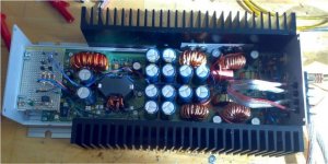
The transformer is made on a Epcos RM14 core with N87 material, it has 2+2 primary windings and 9+9 secondary windings.
The frequency is set to 100kHz (200kHz oscillator)
I suspect that the problem is the transformer itself, looking with the scope at the secondary side i see almost a squarewave of 80Vpp with a big spike touching 100Vpp.
On top of that the transformer becomes quite warm even at idle after some minutes.
I don't understand how could it regulate to +/-50V at idle having only +/-40V at the transformer output. It is maybe the spike that is rectified by the diodes at idle?
Do you think that adding a couple of turns on the secondary side will be effective?
What about leakage inductance, can it be the source of the problem.
This is the only probelm i notice now. I have tried some test on a 4ohm dummy load in bridged mode and even after few minutes nearly at full power nothing heats up significantly.
Please help
thank you
I have finished building the amplifier and I have started the power tests.
When used in bridged mode with 4ohm load the supply rails collapse to 30V (they are normally regulated at 50V). After that
the UVLO of the irs2092 triggers and the amp mutes for around a second.
I have used a 60Ah car battery to do the test and when the UVLO triggers the input voltage measured at the transformer center tap is 11V.
The transformer is made on a Epcos RM14 core with N87 material, it has 2+2 primary windings and 9+9 secondary windings.
The frequency is set to 100kHz (200kHz oscillator)
I suspect that the problem is the transformer itself, looking with the scope at the secondary side i see almost a squarewave of 80Vpp with a big spike touching 100Vpp.
On top of that the transformer becomes quite warm even at idle after some minutes.
I don't understand how could it regulate to +/-50V at idle having only +/-40V at the transformer output. It is maybe the spike that is rectified by the diodes at idle?
Do you think that adding a couple of turns on the secondary side will be effective?
What about leakage inductance, can it be the source of the problem.
This is the only probelm i notice now. I have tried some test on a 4ohm dummy load in bridged mode and even after few minutes nearly at full power nothing heats up significantly.
Please help
thank you
One should use the lowest number of turns without saturation or high core loss, so 2 turns is OK. Fewer turns: lower leakage inductance in general.
But in order to further decrease leakage inductance, primary1 and primary2 needs to be divided into paralell parts (a, b, c...) and twisted p1a with p2a, p1b with p2b, etc... together. This has good effect on efficiency at high current.
Primary cross-section should be a little higher, secondary could be thiner.
Hi Luka,
I have some probelms with my battery, last night I have recharged it and this morning I have done some new tests:
The battery is connected to the amplifier using 2 meters of
6 AWG cables (13mm2 section)
1) Amp running at idle:
- Vbattery=12.68V
- V_center_tap= 12.68V
- Current=1.27A
- VBus=50.1V / -49.9V
- Vsec= 56Vpeak / 58V spike
2) Amp at clipping with 1Khz sinewave in BTL mode 4ohm resitive
load
- Vbattery=11.02V
- V_center_tap=10.8V
- Current= ??? (I have to find a way to measure it probably
using the voltage drop accross the fuse and
wires)
- Vbus=29.7V / -29.6V
- Vsec= 33Vpeak / 48V spike
- Vout=58Vpeak (420Wrms @ 4ohm)
After these tests I think that my battery still has problems, the voltage drops from 12.68V to 11.02V at full load. In any case I think that I can anyway do reliables measurements with that battery because the bottleneck is clearly the transformer.
Vsec is the voltage between the transformer secondary center tap (GND) and the two secondary ends (the ones that goes to the diodes).
On Vsec I see a squarewave (almost) with 33Vpeak with a spike
on the rising edge touching 48V.
I have no snubber on the secondary side, just to snubbers with 5ohm+47nF on the transfomer primary side.
@ pafi
You think that is leakage inductance that is creating the problem? I have more than 20V of voltage drop on each rail at full load...
To wind my transformer I have twisted togheter the 9 primary wires and wound them on the coil former (2 turns, center-tab, 2 turns). Then I have wound the secondary: twisted 4 wires, 9 turns, center-tap, 9 turns.
I will try to rewind the transformer using your suggestion. What do you think about the core I have chosen? You think I should go for a toroid?
Attached you will find a picture of the finished amp.
thank you
Attachments
Pafi, I am trying to understand how you suggest to wind the primary.
Just to be clear if I use 10 wires and I call these wires a,b,c,d,e,f,g,h,i,j I need a total of 20 wires to make the two sides
of the primary. Let's call them a1,b1,...,j1 (for the primary first half) and a2,b2,...,j2 (for the primary second half)
You suggest to twist toghether wire a1 with wire a2, wire b1 with wire b2 and so on.
How can I wind now my transformer?? If I start from the center tap with the wire pair a1 and a2 I have to wind them in the same direction on the coil former (because they are twisted). The other end of wire a1 will be connected to the first primary and wire a2 to the second primary side.
Doing like this the result is two parallel windings that turns on the same direction around the core, it is no more a push-pull transformer.
Am I missing something ? can you please explain me clearly?
Thank you

I have measured the current.
My positive wire + fuse has 6.9mohm of resistance (calculated using the voltage drop at idle with 1.27A).
The voltage drop on the wire at full load is 277mV which gives me
40A.
In any case the efficiency is not bad: I have a total power from the battery of 40A*11V=440W at full load and an output power of
420Wrms.
It gives me about 95% efficiency is it a reasonable number
Of course no heat but also no power  (at least not the power i want....)
I have tried to mount the amp in my car driving a 15" subwoofer, despite the power issue it sounds really load with very defined bass.
I think that when I will fix this transformer issue this amplifier will rock...
(at least not the power i want....)I have tried to mount the amp in my car driving a 15" subwoofer, despite the power issue it sounds really load with very defined bass.
I think that when I will fix this transformer issue this amplifier will rock...
You think that is leakage inductance that is creating the problem? I have more than 20V of voltage drop on each rail at full load...
Yes, very probably. But drop is mainly not because of leakage between P1 and P2, but leakage between primary and secondary, so you should place them closer to each other too. How to do this? For example: divide secondary into two halfs (parallel or in series, it's up to you), one under the primary, and the other one over the primary! You can even divide coils into many layers, and interleave them.
Doing like this the result is two parallel windings that turns on the same direction around the core, it is no more a push-pull transformer.
Simply connect end of a1 to the beginning of a2!
Actually twisting is not neccessary, it only represents the rule that a1 and a2 should be side-by-side. A1 and a2 doesn't have to be single wire, they can be multiples (eg. triplets) too.

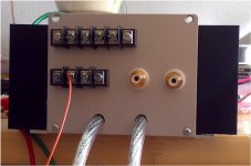
Picure of the back panel
First row are the speakers output connectors,
second row is the remote switch on (both terminal in parallel).
On the right there are the two RCA input connectors.
No connectors for the 12V power supply, just two 6 AWG cables
direcly soldered on the PCB.
First row are the speakers output connectors,
second row is the remote switch on (both terminal in parallel).
On the right there are the two RCA input connectors.
No connectors for the 12V power supply, just two 6 AWG cables
direcly soldered on the PCB.
Attachments
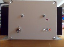
Picture of the front panel:
Red clipping indicator led (I have used a slightly modified version of the clipping detector of sound.westhost.com; it works very nice).
Main power switch (it breaks the remote line, not the 12V of course....) I use it when I remove the subwoofer from my car so that I don't need to disconnect the amp from the radio
Main green power led, it is on when the amp is on of course.
Red power supply protection led (it acts on over temperature and when a DC offset >4V is detected at the output). When on the power supply is switched off for 5 seconds and then turned back on.
Amber amplifer protection led: the bus voltage is detected and when it is >55V or <30V the amplfier section is switched off for 5 seconds and then turned back on. Now I have removed that protection because my voltage rails are falling down to 29V at full load
Attachments
 amp, You seem to have lot of of protections, which is very good
@ Pafi
ok now it is clear (I hope) I will tell you something when I will start to wind the new transformer.
You suggest to keep the same number of turns (2+2 on primary and 9+9 on secondary) or to increase the number (I don't know if it is possible on my transformer, not enough room).
Keeping 2+2 turns on primary, what about increasing the secondary to 10+10 or 11+11 to have more marging. The PSU is regulated on the positive rail. After the diodes I have a 47uH inductor and 6x1500uF capacitors (on each rail). The PWM IC will regulate to 50V so that even if I have more turns on the secondary side the feedback will regulate to 50V.
On top of that I have an auxiliary winding to create a 12V supply referred to the -50V. It is used for the class-D gate drive of the IRS2092. Being a low power winding (typically 50-60mA) I don't think it will create problems.
What do you think about it?
thank you
@ luka
If you are interested in how I have implemented the protection don't check the schematics at the beginning of the thread, it is the first version full of mistakes.... Just ask me and I will give you the corrected schematics
- Status
- This old topic is closed. If you want to reopen this topic, contact a moderator using the "Report Post" button.
- Home
- Amplifiers
- Class D
- Class-D Amp with IRS2092