The only other thread I could find on this chip was asking for a PCB, there were no replies...
I did a Google search 'Tripath TA2024' because I was looking to buy some chips, I found this Maxim chip offering itself as an alternative.
It's a class-D spread spectrun audio amp, with a comparable output, but that's pretty much where the resemblance ends. This runs up to 25V and is filterless, hence not really requiring a PCB as there are just a few caps at the inputs and across the power rails. It just sends the supersonic spread spectrum PWM to the speaker and lets it get on with it. Minimalist or what?
Does anybody know if it is possible to buy the Tripath chip still? I heard the company went out of business and was bought up. I been waiting for a board from sureelectronics, but they said they were waiting for stock. I ordered a Sonic Impact, just to be sure I get at least one.
Anyway, Maxim are sending me two of these chips I hope. They been out for a while so I guess if they were really hot there would be some posts about them. If the Tripath chip turns up in some incarnation, I'll be able to compare them.
This device comes in a 32-Pin TQFN package with a copper paddle. You DO need a proper PCB to use this IC...
For starters, and to quote the datasheet: "The exposed pad is the primary route of keeping heat away from the IC. With a bottom-side exposed pad, the PC board and its copper becomes the primary heatsink for the Class D amplifier."
Secondly, although the design is minimalist and requires very few components, it is still a class-D amp. What this means is that both the gound and Vdd pins, will have high current pulses with ultra-fast rise and fall times. This essentially means that even nanohenries in any wiring around those pins will create large voltage spikes that at best will cause a lot of distortion. At worst, the chip may be damaged.
A double sided board is a bare minimum, with a multilayer board with a dedicated ground and power planes the best.
Aaaah!
Not the first time I been caught out by the decreasing size of packages, I just saw the familiar 32 pin square outline and thought it was a QFP32. I've got some charge-pump LED drivers here that I sampled only to discover that these 12-pin devices are only 3x2mm. Those are a bit small for laser-printed PCBs.
3 inches of speaker wire could be a problem too... ...but the datasheet says only 'use a ferrite bead filter... snip ...or when long leads connect the amplifier to the speaker.' The '3 in' reference is to the conditions they employed for EMC test. I don't intend to be submitting for EMC test.
Anyway, I'm not one to give up easily, I bought a nice radiant cooker, I've successfully surface-mounted a few things using it. It's entirely possible to route 8x12 thou traces into each side of a 7mm square, my router doesen't even throw a design rules violation at standard settings. I've forced it to accept much smaller and tighter traces.
And things aren't that bleak, lots of the pins are side-by-side doubled, in fact it might still be possible to solder the components directly to the chip and glue the heatsink on with thermal epoxy.
Unlike the LED driver chip, this one has pins that are exposed on the side of the package. Gluing the heatsink works surprisingly well with Cree and Seoul Semi LEDs and failing all else you can rub the PCB down to a sliver on some abrasive and glue that to the heatsink. As far as components go, there are only the PSU decoupling caps, the DC blocking at the input and the charge pump. In fact, the more I look at it, the more do-able it looks...
w
wakibaki said:
It's a class-D spread spectrun audio amp, with a comparable output, but that's pretty much where the resemblance ends. This runs up to 25V and is filterless, hence not really requiring a PCB
Once you go more than a few centimeters you need an output filter.
I got the chips from Maxim but due to some quirk 2xMax9703 arrived, could be finger trouble on my part. These are the mono flavour.
Anyway these are 5mm on an edge w/32 pins. I'm not going to try to solder direct to the chip. In some ways mono is better, I could mount them direct to the drivers and avoid the issues with 3cm lead lengths... ...although I'm fairly sure I've seen more than 3cm of litz as lead-in wire to the coil on many drivers. The issues seem to be more around EMC rather than sonic.
Here's a picture of the chip + package outline with a DIL PIC for scale. The layout and sourcing the components is turning out to be a real pain. The chip itself is dwarfed by even SMT caps. You can put 3 traces the width of one of this thing's pads through the space between a 1206 cap's pads. It's not easy to get 25V working in a 0u1 0603. There's the heatsinking copper on the board, plus trying to maintain some decent width in the signal tracks plus trying to keep the inductance of the cap tracks low and the current loop area small.
I guess I'll make the bottom layer of the board GND, connect the chip's heatsink pad to VDD and floodfill the top with that. If I don't route any tracks on the bottom then I don't have any registration problems. I'll punch a via through to GND as close as I can get it to the chip's ground pins, I don't mess with via-in-pad for homemade boards.
In fact here it is, at 2*lifesize...
It's set for spread spectrum and max gain.
At most, 4 sq cm of copper on the board for direct heatsinking. The thermal relief round the cap pads is impeding the flow into the rest of the layer. Maybe I'll just turn that off, or block up the mask with a pen.
w
Anyway these are 5mm on an edge w/32 pins. I'm not going to try to solder direct to the chip. In some ways mono is better, I could mount them direct to the drivers and avoid the issues with 3cm lead lengths... ...although I'm fairly sure I've seen more than 3cm of litz as lead-in wire to the coil on many drivers. The issues seem to be more around EMC rather than sonic.
An externally hosted image should be here but it was not working when we last tested it.
Here's a picture of the chip + package outline with a DIL PIC for scale. The layout and sourcing the components is turning out to be a real pain. The chip itself is dwarfed by even SMT caps. You can put 3 traces the width of one of this thing's pads through the space between a 1206 cap's pads. It's not easy to get 25V working in a 0u1 0603. There's the heatsinking copper on the board, plus trying to maintain some decent width in the signal tracks plus trying to keep the inductance of the cap tracks low and the current loop area small.
I guess I'll make the bottom layer of the board GND, connect the chip's heatsink pad to VDD and floodfill the top with that. If I don't route any tracks on the bottom then I don't have any registration problems. I'll punch a via through to GND as close as I can get it to the chip's ground pins, I don't mess with via-in-pad for homemade boards.
In fact here it is, at 2*lifesize...
It's set for spread spectrum and max gain.
An externally hosted image should be here but it was not working when we last tested it.
An externally hosted image should be here but it was not working when we last tested it.
An externally hosted image should be here but it was not working when we last tested it.
At most, 4 sq cm of copper on the board for direct heatsinking. The thermal relief round the cap pads is impeding the flow into the rest of the layer. Maybe I'll just turn that off, or block up the mask with a pen.
w
Maxim call these 'speaker amplifiers' presumably because they make the most economic sense when mounted very close to the driver.
Some DS PCBs.
These things are tiny. Me and my big mouth! ...and my big banana fingers...
I might try etching a solder paste stencil in very thin shim brass or copper foil.
I made the boards this morning, then I remembered about turning off the thermal relief on the cap pads. Never mind, I'll patch in a bit of copper foil.
An externally hosted image should be here but it was not working when we last tested it.
Some DS PCBs.
These things are tiny. Me and my big mouth! ...and my big banana fingers...
I might try etching a solder paste stencil in very thin shim brass or copper foil.
I made the boards this morning, then I remembered about turning off the thermal relief on the cap pads. Never mind, I'll patch in a bit of copper foil.
Ah, this is for the 9703.
I guess this is the one you're looking for
The image below is 2x life size.
I've attached a .prn file which you can send to your printer, remember the image is mirrored, as this is the top copper.
Bottom copper is GND, top filled area is Vdd.
I haven't got a 9704 so I can't check the pad spacing and dimensions against the chip, the datasheet is hard to understand as the description is generic for 32-44 pin devices, plus this is the limit of resolution for my router. So bear this in mind and check the chip against the pattern.
I have just used 1206 sizes for the caps, except for the big electrolytic, I used a TANT package there although these don't go high enough in voltage. You can still probably accommodate a wide range of SMT and THT caps on these pads with a bit of fiddling.
I HAVE NOT BUILT THIS CIRCUIT! THERE MAY BE ERRORS! Please tell me if you discover any.
THe gain is set to maximum (G1,G2 LO), and mode to spread spectrum (FS1, FS2 HI).
I did some experiments yesterday with a hot-air gun, I can easily get regular solder to melt without cooking the board by heating from below, so I'll probably use this for soldering instead of the cooker. By keeping the heatgun at a distance I can pre-heat (soak) the board briefly and then bring it in closer for the melt, then switch to cold.
The big difficulty is getting solder on the pads and registering and placing the chip. I'm thinking about some kind of small scale dip or wave to pre-tin both board and chip cleanly. Fiddling around with an iron and solder-wick is not getting there.
I guess this is the one you're looking for
An externally hosted image should be here but it was not working when we last tested it.
An externally hosted image should be here but it was not working when we last tested it.
The image below is 2x life size.
An externally hosted image should be here but it was not working when we last tested it.
I've attached a .prn file which you can send to your printer, remember the image is mirrored, as this is the top copper.
Bottom copper is GND, top filled area is Vdd.
I haven't got a 9704 so I can't check the pad spacing and dimensions against the chip, the datasheet is hard to understand as the description is generic for 32-44 pin devices, plus this is the limit of resolution for my router. So bear this in mind and check the chip against the pattern.
I have just used 1206 sizes for the caps, except for the big electrolytic, I used a TANT package there although these don't go high enough in voltage. You can still probably accommodate a wide range of SMT and THT caps on these pads with a bit of fiddling.
I HAVE NOT BUILT THIS CIRCUIT! THERE MAY BE ERRORS! Please tell me if you discover any.
THe gain is set to maximum (G1,G2 LO), and mode to spread spectrum (FS1, FS2 HI).
I did some experiments yesterday with a hot-air gun, I can easily get regular solder to melt without cooking the board by heating from below, so I'll probably use this for soldering instead of the cooker. By keeping the heatgun at a distance I can pre-heat (soak) the board briefly and then bring it in closer for the melt, then switch to cold.
The big difficulty is getting solder on the pads and registering and placing the chip. I'm thinking about some kind of small scale dip or wave to pre-tin both board and chip cleanly. Fiddling around with an iron and solder-wick is not getting there.
I just built up a MAX9709, with an external filter and gain selector.
To attach most of the parts I just used a little solder paste and threw the board in a toaster oven till it melted. Worked like a charm. (I found a free one on craigslist just for surface mount soldering)
How do you guys find the sound of these? I found them a little harsh. i'm hoping to warm it up a bit with some lag compensation feedback. It's got a more than enough gain, so I figure I minaswell take some of that away in place of linearity.
Cheers mates,
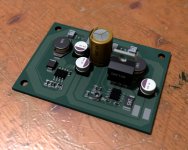
even this topic is rather "old", i just want to show my MAX9704-layout and prototype. PCB is done from FR4 35µm, single layer.
Circuit:
Fixed-Gain, spread-spectrum-mode, no standby.
Eagle:
TQFN-32 soldering on a Weller WQP 4000 SOPS
Prototype:
Under full-load i get ~42°C on the pcb's bottom-side. (at 22°C surrounding)
Cheers, Christian
even this topic is rather "old", i just want to show my MAX9704-layout and prototype. PCB is done from FR4 35µm, single layer.
Circuit:
An externally hosted image should be here but it was not working when we last tested it.
Fixed-Gain, spread-spectrum-mode, no standby.
Eagle:
An externally hosted image should be here but it was not working when we last tested it.
An externally hosted image should be here but it was not working when we last tested it.
TQFN-32 soldering on a Weller WQP 4000 SOPS
An externally hosted image should be here but it was not working when we last tested it.
Prototype:
An externally hosted image should be here but it was not working when we last tested it.
An externally hosted image should be here but it was not working when we last tested it.
Under full-load i get ~42°C on the pcb's bottom-side. (at 22°C surrounding)
Cheers, Christian
doctormord, very nice work !
Your circuit doesn't show any output filter, yet the wires to the speaker seem to be quite long.
How does it sound without the filter ?
Your circuit doesn't show any output filter, yet the wires to the speaker seem to be quite long.
How does it sound without the filter ?
The chip uses a spread spectrum technique to mitigate the need for an output filter. No idea how effective it is.
The filter is needed so that it "smooths" the signal and cuts off the frequencies outside the audio band.
If it is absent, then the poor speaker + cables + parasitics have to perform this function which they might perform poorly.
In other words, you should not care about the filter because you want to keep the cell phones interference free (or not only).
You should care about the filter because the sound might be much better that without.
Can anyone argue that the sound quality is the same with/without the filter ?
Regarding to the datasheet, output filtering is not needed if cables keeped short and the speakers impedance is in a range of 30-100µH which applies to most of 8ohms+ speaker chassis.
If additional EMI-filtering is needed (long cables, "bad" layout), output filtering needs to be applied. Sound-quality "should" not be affected, as the switching-frequency is at a minimum of 470kHz
As for the 3d-rendering, this is done in eagle-3d with custom setup.
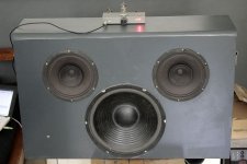
Actually im running a setup constisting a 9704 with a tube prestage (E88C) & 2 simple-switchers.
The 9704 is powered by 12V directy, the E88C is running at 100V anode-voltage (MAX1771 step-up) and 6.3V heater (MP1591 step-down). Everything housed in a small metal-case with no problems.
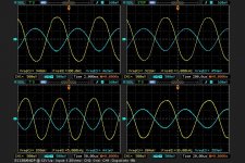
See the attached picture for the amp + the dual simple switcher pcb and frequency response of tube-buffer.
Cheers doc
Source: Maxim 9704 Datasheet, Page 10The MAX9703/MAX9704 do not require an output filter.
The devices rely on the inherent inductance of the
speaker coil and the natural filtering of both the speaker
and the human ear to recover the audio component
of the square-wave output. Eliminating the output filter
results in a smaller, less-costly, more-efficient solution.
Because the frequency of the MAX9703/MAX9704 output
is well beyond the bandwidth of most speakers,
voice coil movement due to the square-wave frequency
is very small. Although this movement is small, a speaker
not designed to handle the additional power can be
damaged. For optimum results, use a speaker with a
series inductance > 30μH. Typical 8Ω speakers exhibit
series inductances in the range of 30μH to 100μH.
Optimum efficiency
If additional EMI-filtering is needed (long cables, "bad" layout), output filtering needs to be applied. Sound-quality "should" not be affected, as the switching-frequency is at a minimum of 470kHz
As for the 3d-rendering, this is done in eagle-3d with custom setup.
Actually im running a setup constisting a 9704 with a tube prestage (E88C) & 2 simple-switchers.
The 9704 is powered by 12V directy, the E88C is running at 100V anode-voltage (MAX1771 step-up) and 6.3V heater (MP1591 step-down). Everything housed in a small metal-case with no problems.
See the attached picture for the amp + the dual simple switcher pcb and frequency response of tube-buffer.
Cheers doc
Attachments
- Status
- This old topic is closed. If you want to reopen this topic, contact a moderator using the "Report Post" button.
- Home
- Amplifiers
- Class D
- Maxim MAX9704 - anybody built one?