A few years ago I used to work for a local band that had a few Peavey CS-800 in their PA setup, and other similar amplifiers. I mean the good old CS-800, the one with the fashion die cast front plate using 5U rack space and weighting approx 20Kg. It was really heavy and bulky for an amplifier producing only 250W per channel at 8 ohm and 400W at 4 ohm.
I can assure that carrying that kind of gear back and forth (truck, stage, truck, stage...) teaches you some very valuable lessons about amplifier design that can't be found on any text book or forum. Every amplifier designer should go through this experience.
I wish I had the class D knowledge that I have now back then... Now I'm working on reasonably "portable" stuff capable of producing 2KW or 3KW without even a fan
I love my QSC's, I have 3 of the PLX1804 amps. thats 5.4kw of power. in 6 rack spaces and the whole things weighs under 40lbs!!!!
Thats HALF the weight of ONE old school amp! and you just got to love an amp that puts out 900 watts per channel at 4 ohms and weighs 13LBS!!!!
Not to mention that QSC has a KILLER employee Dealer program that allows people that work for QSC dealers to buy there amps and a huge discount. I got mine for half of street retail!
Not to mention QSC has the best support of there products! They even have an online forum for techs to talk to REAL techs about servicing there amplifiers. and not "just send it in" i mean, check q102 and r13 and voltages should be type real help. NO ONE else in the biz has that.
I have a strong feeling that we have some of the staff members from QSC sales dept here on this very thread..........
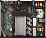
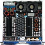
This PL380 features all smd construction, good for marketing hype, but not that much reliable when it comes to survive transportation jobs loading, unloading. I have seen many bad smd components displaced/broken pcb pads just due to vibration on plx3602.
Evita this amplifier conducts huge EMI, we had it tested on live stage and found that it interferes greatly with cordless mics which are working in VHF band. Their is no proper uniform groundplane on the PCB, but it still amazes me that this thing uses 4-Layer board. . The Filter Toroids are mounted very near to the analog signal processing pre-amp opamps, therefore all the small-signal traces are highly contaminated. Idle Rails are +/-190V sag to 120V when subjected to 100mS brust of 1KHz at 2 ohms load. I can't understand how they are stating 4KW@2ohms per channel.
This PL380 features all smd construction, good for marketing hype, but not that much reliable when it comes to survive transportation jobs loading, unloading. I have seen many bad smd components displaced/broken pcb pads just due to vibration on plx3602.
Evita this amplifier conducts huge EMI, we had it tested on live stage and found that it interferes greatly with cordless mics which are working in VHF band. Their is no proper uniform groundplane on the PCB, but it still amazes me that this thing uses 4-Layer board.
. The Filter Toroids are mounted very near to the analog signal processing pre-amp opamps, therefore all the small-signal traces are highly contaminated. Idle Rails are +/-190V sag to 120V when subjected to 100mS brust of 1KHz at 2 ohms load. I can't understand how they are stating 4KW@2ohms per channel.fredos said:Still stable with no load? What happen if you drive it, maybe at 30% of full power and remove load? And if you drive it at HF and remove load? Just curiosity...
Fredos
They have used an aluminium encapsulted heatsink mounted 4.7E 200W resistor in Zobel just for that purpose............
Attachments
Workhorse said:Idle Rails are +/-190V sag to 120V when subjected to 100mS brust of 1KHz at 2 ohms load. I can't understand how they are stating 4KW@2ohms per channel.
yeah ... that is very suspicious indeed
from the layout it doesn't look like the amp was built from the ground up to deliver 8000 watts but rather looks like they simply took a PLX 3600 and turned it into a class D amp with some boost in output resulting from it
maybe they took 3600 watts multiplied by 85% efficiency and divided by something like 40% efficiency and declared that the new amp is thus 8000 watts
lol ...does anybody have an image of an I-Tech 8000 internal layout to compare this with ?
according to the website specs. the PL380 is rated for 2500 watts P/Ch at 4 ohms. and there is a note by the 2 ohms spec of 4000 watts that says *Burst mode testing required due to AC service current limitations.
So assume a very very short burst at that. what maybe 10-100ms or something? I wouldn't consider this to be a 4Kw per channel amp by any means. 2.5K yes.
Where do you find the 100 amp spec? i see a current draw listing of 18amps and there is a not that talks about a 30 amp cutback circuit. but im not sure where the 100 amp spec came from???
Zc
The best way to understand this subject it to measure amplifier current consumption (peak and average) under real world working conditions (speakers and music). I encourage everybody to do so. Results have little to do with the assuptions commonly made by most people in these forums.
Zero Cool said:according to the website specs. the PL380 is rated for 2500 watts P/Ch at 4 ohms. and there is a note by the 2 ohms spec of 4000 watts that says *Burst mode testing required due to AC service current limitations.
So assume a very very short burst at that. what maybe 10-100ms or something? I wouldn't consider this to be a 4Kw per channel amp by any means. 2.5K yes.
Where do you find the 100 amp spec? i see a current draw listing of 18amps and there is a not that talks about a 30 amp cutback circuit. but im not sure where the 100 amp spec came from???
Zc
What I read:
http://www.qsc.com/products/amps/powerlight3/powerlight3.htm
Per channel it's rated.
4000*
EIA 1 kHz 1% THD
* Burst mode testing required due to AC service current limitations
And from: http://www.qsc.com/pdfs/manuals/PL3_User_Manual_RevB.pdf
Look for the table under "AC Mains Current Draw"
Which shows 2 x 2ohms at 100A for "Full Power Sine Wave"
So it's "EIA", and they may be on the loose side of the standard. I wonder what it would be for "FTC"? At least they're measuring to a standard.
Ultimately I have no problem with designing a product to meet certain application specific performance requirements. However it is a slippery slope made even more slippery when the marketing people get their hands on things.
"Burst mode testing required due to AC service current limitations."
"Idle Rails are +/-190V sag to 120V when subjected to 100mS brust of 1KHz at 2 ohms load."
Put the two together and the first one needs to be restated as.
"Burst Mode testing required due to shoddy design of the SMPS operated open loop because we don't know how to design one and ripped off what everyone else is using"
Look at the flash presentation again.....
http://www.qsc.com/products/amps/powerlight3/PL380_tour.htm
Can you see any output filter inductors in the power supply itself. You can't because they are not there. They are not there because the pro-audio johnnies don't have a basic clue. Let's not talk about capacitor lifetimes when you hammer them with extreme ripple currents.
Pre filter feedback indeed.
Someone else has mentioned EMC performance. The flash presentation proudly announces measures taken to deal with such issues. They don't work because the pro-audio johnnies don't have a basic clue.
I wouldn't push things but this might degenerate into another Nu-Force thread.
I'm a coward so I'll run away now.
DNA
I was really expecting this amplifier to be more "high tech".
A PFC-style power supply with pseudo-regulated output wouldn't have hurt anybody. They used this technology in other amplifiers but it seems that they weren't able to achieve the degree of reliability expected in a touring amplifier. Why? They have plenty of development resources. For example, I have developed a PFC capable of 5KW day and night at 230V input in my home lab with far less resources (now I'm going through the hell of adding a "green" low idle power mode).
A self oscillating class D control scheme wouldn't have hurt anybody either. Then again, if DIYers are starting to understand this technology and take advantage of it, why big companies doesn't? It solves many problems related to the good old clocked approach.
The EMI issues are somewhat more puzzling. There are consistent and repeatable tricks to tame EMI ringing to just one or two cycles and confine the RF action in small circuit loops. Since I know some of these tricks, I was expecting the people that designs these amplifiers to know them all. It seems that they doesn't
"Burst Mode testing required due to shoddy design of the SMPS operated open loop because we don't know how to design one and ripped off what everyone else is using"
If they suck so bad, why are they so desireable to copy:
Camco/Ashly
Alab-pro
If you look at the internals and PCB layouts of these amplifiers, they look EXACLY the same as QSC's PLX. I'm pretty sure QSC was first developing their supply (crappy as it may be)at least 10 years ago. Just wait a few months and I'll bet companies will be knocking off this Class-D design as well, crappy design or not.
Also, it can be beneficial to have some power supply sag so your 2 ohm and 8 ohm powers match up a bit better than if you regulated at a fixed voltage although I agree 70 volts of sag is rediculous!
By the looks of it, we may have an amp soon that will need a 32amp or 63amp outlet that is normally used by the lighting guys....
I don't really see the need for so much power unless you are building a rig that can be heard by thousands of people, or using inefficient cabs...
I don't really see the need for so much power unless you are building a rig that can be heard by thousands of people, or using inefficient cabs...
Actually, here in the states a lot of pro audio and most theater audio is already using 230v 20A circuits to power the newer amps and really most Meyer products. Far more efficient power distribution and the only way to get full power out of these switch mode amps like the labGruppen, Powersoft, Camco, MC2, etc.
Eva said:
...
I'm going through the hell of adding a "green" low idle power mode).
...
Yes!!!!
I want this. Hurry up an release a product!
Pro-Audio, theaters, etc. all need it.
raintalk said:
Yes!!!!
I want this. Hurry up an release a product!
Pro-Audio, theaters, etc. all need it.
Hey thanks, one needs some motivation to write two or three thousand lines of PIC microcontroller assembler
ionutgaga said:Have a look on this: PowerSoft 2 x 9kw @ 2ohm....
you forgot to mention that powersoft amp is also 1RU high so those parts (caps, heatsinks) are twice as small as they look
Zero Cool said:I wouldn't consider this to be a 4Kw per channel amp by any means. 2.5K yes.
ok i agree, its something like a 5KW or 6KW amp not a 8KW one ..
i mean here:
http://www.crownaudio.com/amp_htm/itech.htm
crown does not try to use 20 millisecond burst power as the power rating of the amp ... so PL 380 really has about 5500 I-Tech watts ...

I will try to shed some light on the power rating discussion with a practical example...
The following plots are frquency response and electrical impedance simulations of the bass horns that I'm planning to build. They are intended for high SPL PA use. I would like to build four cabinets but I only have budget and storage for two. Also, I recently did a good deal on two nice 15 inch PA woofers...
This is the frequency response of a single bass horn standing in the floor outdoors:
This is the electrical impedance of a single bass horn standing in the floor outdoors:
This is the frequency response of two bass horns standing together in the floor outdoors:

This is the electrical impedance of two bass horns standing together in the floor outdoors:
Some facts about these plots:
- There is substantial ripple on frequency response, particularly for a single horn, but the valleys in SPL actually correspond with peaks in electrical impedance so equalizing them with a DSP does not cost any extra amplifier power!! Only extra amplifier output voltage swing is required.
- The voice coil resistance of my woofers is 5.3 ohms, but the average impedance in the 35Hz to 270Hz passband is over 10 ohms!! And it is mostly reactive!! It's nearly 15 ohms for two cabinets together!! Where is the power?????
The answer is: There is actually very little power to deal with!!!
I will use one class D amplifier to drive each of the two cabinets. With these bass horns as a load, ecah of the amplifier channels will provide approx. +/-160 volts of peak output swing of music (bass) without any heatsink, just with the metal tabs of the power transistors exposed to the air
BTW: Essentially this is what I have to say to old-school amplifier designers
The following plots are frquency response and electrical impedance simulations of the bass horns that I'm planning to build. They are intended for high SPL PA use. I would like to build four cabinets but I only have budget and storage for two. Also, I recently did a good deal on two nice 15 inch PA woofers...
This is the frequency response of a single bass horn standing in the floor outdoors:
This is the electrical impedance of a single bass horn standing in the floor outdoors:
This is the frequency response of two bass horns standing together in the floor outdoors:
This is the electrical impedance of two bass horns standing together in the floor outdoors:
Some facts about these plots:
- There is substantial ripple on frequency response, particularly for a single horn, but the valleys in SPL actually correspond with peaks in electrical impedance so equalizing them with a DSP does not cost any extra amplifier power!! Only extra amplifier output voltage swing is required.
- The voice coil resistance of my woofers is 5.3 ohms, but the average impedance in the 35Hz to 270Hz passband is over 10 ohms!! And it is mostly reactive!! It's nearly 15 ohms for two cabinets together!! Where is the power?????
The answer is: There is actually very little power to deal with!!!
I will use one class D amplifier to drive each of the two cabinets. With these bass horns as a load, ecah of the amplifier channels will provide approx. +/-160 volts of peak output swing of music (bass) without any heatsink, just with the metal tabs of the power transistors exposed to the air
BTW: Essentially this is what I have to say to old-school amplifier designers
- Status
- This old topic is closed. If you want to reopen this topic, contact a moderator using the "Report Post" button.
- Home
- Amplifiers
- Class D
- QSC PL380 amp