Hi Everyone !
Well, I'm evaluating an amp with TDA8920BJ, it runs at 327Khz, and sounds surprisingly good.
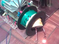
I built ALL the output inductors, and all inductors that had a small hole, heated a LOT.
First I built one with 18AWG wire, with a resonable good size hole, and it ran pretty hot. Then I thought that it was the wire loss, and I built another with 14AWG wire, with a smaller hole. It heated MORE
Then I built a BIG SIZE HOLE inductor using 16AWG wire, and it runs TOTALLY COLD !
So I built another, with a medium size hole, using the same wire (16), and it ran WARM...
WHAT makes the inductor run HOT when the hole is small ?
Ok, big hole air core inductor works FINE, and of course it sounds veeeery good... But it's damn big, and might radiate a NASTY EMI...
I soldered one LED on one of the hot inductors that I don't use anymore, and if I put it close to the hole of the big inductor, the led lights up... And yes, I BURNED the led !
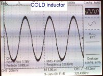
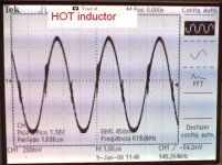
The big hole inductor have a perfect waveform at the output, and the smaller hole inductors (those that heats) shows a deffective waveform.
I ordered this inductor from Farnell:
http://uk.farnell.com/jsp/search/productdetail.jsp?sku=1077056
My GOOD (incredible GOOD !) working inductor is just FUNNY It puts out 1.16v of residual PWM, sounds great, and shows a perfect waveform !
Let's see what happens with the ordered inductor...
But, my DOUBT is... WHY air core inductors with small hole runs HOT
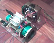
Here is my TDA8920BJ under testing:
At the left, is the small inductor that runs warm, and at the right there's the big inductor that runs totally cold.
Well, I'm evaluating an amp with TDA8920BJ, it runs at 327Khz, and sounds surprisingly good.
I built ALL the output inductors, and all inductors that had a small hole, heated a LOT.
First I built one with 18AWG wire, with a resonable good size hole, and it ran pretty hot. Then I thought that it was the wire loss, and I built another with 14AWG wire, with a smaller hole. It heated MORE
Then I built a BIG SIZE HOLE inductor using 16AWG wire, and it runs TOTALLY COLD !
So I built another, with a medium size hole, using the same wire (16), and it ran WARM...
WHAT makes the inductor run HOT when the hole is small ?
Ok, big hole air core inductor works FINE, and of course it sounds veeeery good... But it's damn big, and might radiate a NASTY EMI...
I soldered one LED on one of the hot inductors that I don't use anymore, and if I put it close to the hole of the big inductor, the led lights up... And yes, I BURNED the led !
The big hole inductor have a perfect waveform at the output, and the smaller hole inductors (those that heats) shows a deffective waveform.
I ordered this inductor from Farnell:
http://uk.farnell.com/jsp/search/productdetail.jsp?sku=1077056
My GOOD (incredible GOOD !) working inductor is just FUNNY
It puts out 1.16v of residual PWM, sounds great, and shows a perfect waveform ! Let's see what happens with the ordered inductor...
But, my DOUBT is... WHY air core inductors with small hole runs HOT
Here is my TDA8920BJ under testing:
At the left, is the small inductor that runs warm, and at the right there's the big inductor that runs totally cold.
Attachments
nando!
The smaller inductor have a higher flux density (constant magnetic energy in smaller place -> higher flux density). A bigger part of the flux penetrates into the wire and causes eddy current, than in the case of bigger choke.
Use litze wire! (...and RM style ferrite core with big air-gap.)
The defect in the waveform caused by stray capacitance.
Physics
Same length of same wire, same gauge = same resistance + same current (or voltage) = same heat.
If you're building inductors with the same inductance but a different form factor, and using the same wire, then the length will be different, the resistance will be different, and the Q factor will be different.
If you build coils with the same wire and different form factors then the inductance will be different. (WTF?)
You can build coils with the same Q factor and inductance and different form factors, but then the current handling will be different.
So first make sure you're really comparing like for like.
It's just possible that work hardening the wire by pulling it into a smaller radius has an effect on the resistance. Measure the resistance of both coils.
If you're coupling energy into something lossy then IT will heat up, but not the coil.
It can be quite surprising how much the surface area changes as you pack the wire closer, and this obviously has an effect on equilibrium temperature.
An air core inductor for this application is not the best option...by far.
1) As poobah explained, air cores radiate flux everywhere. This is not only EMI, but real interference to your very own circuit.
2) The permeability of air is 1. High frequency materials have permeabilities of 100 or more, meaning that for a given form factor, you'll need far less turns to achieve the same inductance.
And less turns means less wire length, which means lower resistive losses and heat.
3) An added bonus is that your inductor will be substantially smaller.
You are dealing with ohmic thermal characteristics. The Flux from an air core is very dispersed and until you have exceeded the saturation point no significant heat is produced. The problem you are seeing is how much surface area you have to dissipate the heat with. Watts per sq cm of area.
If you are dealing with high speed inductors, meaning a switch mode power supply and need high inductance, relatively, try using a ferrite E core, without an I. Essentially infinite gap, so very close to non saturable. Same holds true for audio inductors and steel laminations.
In both cases the permeability of the window collects and organizes the coil flux, eliminating clumping of field structure. You have all experienced this, if you have unwound an air coil and measured turn by turn, only to discover that it is not actually predictable, just how much the inductance will drop, as the formula would lead you to believe. Adding core that cant saturate, until the coil is glowing red hot, will smooth out your crossover, or remove ghost signals from high frequency inductors.
Bud
Take a look at both wave forms. In both cases the same problem is occuring... just at different levels. If the inductor is the problem here... and it seems to be... then magnetic coupling into the circuitry is likely the cause. In both cases, the weirdness is occuring where change in flux, and therefore induced voltages, in nearby components is the greatest.
Eddy currents could indeed the explain the heating. provided the wire gauge is the same in both coils. I would still bet the difference in surface area is a big factor.
And YES, there is no good reason to use air core here. Compared to air... some sort of core would reduce the "gap" in the magnetic circuit. The would allow much more inductance with less wire.
Add some wires and get those coils AWAY from the rest of the circuit. Then stick a screwdriver or pliers in the "holes" and listen...
Inductors don't act as inductors all the way up in frequency, they are only good up to acertain frequency above which they become capacitors. The point where this transition happens is called "resonant frequency", and yes, inductors act as nice capacitors above resonance.
What you are seeing in the oscilloscope is high frequency leaking through the capacitive part of your inductors. There are probably some traces of EMI ringing too and you should damp it and prevent it from escaping out of the PCB through the wires (ferrite beads may help with this).
When you design a class D output inductor, you have to aim at low capacitance and a high resonant frequency. The easiest way to achieve this is with a single layer winding (plain magnet wire) on a suitable RF iron powder toroid.
Another alternative are gapped ferrites, but while this usually results in better linearity, it usually requires litz wire and results in more capacitance and a lower resonant frequency because one winding layer is usually not enough.
In your air core inductors, the number of layers and the way of winding them matters a lot for capacitance and resonant frequency. You have to avoid zig-zag winding because this puts the beginning of one layer and the end of the next layer together resulting in more capacitive coupling and RF leaking though the inductor. Z winding is better because it puts the beginnings of all the layers in one side and the ends in the other. Another alternative is "random" winding that consists in using a single "fuzzy" layer where electrically adjacent turns are closer and/or overlapped.

- Status
- This old topic is closed. If you want to reopen this topic, contact a moderator using the "Report Post" button.
- Home
- Amplifiers
- Class D
- Air Core inductor: Hole Size ! (waveforms shown)