I've got my first class-D amp going. It's a triangle wave, carrier based design. So far so good.
The FET's are running very cool at idle (although it's in my unheated garage - you haven't lived until you debug in 30 degrees F ) Anyway, the FET's are cool to the touch, but the torroid is warm. How warm? I don't have a thermo probe handy, but it's rather warm to the touch but not buring. Is that typical?
Also, what is the usual residual output voltage? I have 1V p-p sinewave at around 400Khz.
Nothing yet is optimized. This is just my initial observations.
The FET's are running very cool at idle (although it's in my unheated garage - you haven't lived until you debug in 30 degrees F
) Anyway, the FET's are cool to the touch, but the torroid is warm. How warm? I don't have a thermo probe handy, but it's rather warm to the touch but not buring. Is that typical?Also, what is the usual residual output voltage? I have 1V p-p sinewave at around 400Khz.
Nothing yet is optimized. This is just my initial observations.
Nice work gene. So what type of construction method did you use - p2p, breadboard, pcb? Any more details on parts you used, schematic, pictures, etc?
Depending on the core type, size, and windings, warm to the touch can be ok. Normally you want the coil to be cool when idling though.
Depending on the core type, size, and windings, warm to the touch can be ok. Normally you want the coil to be cool when idling though.
for now, it's a point-to-point layout. For something that started out really neat, it's become a managable mess. I first built a triangle wave generator on it's own board to test out that function. Then I built up the main portion.
I didn't mention this, but it also includes a preamp as well. Sadly, my first attempt at the preamp sucked and I wish I did it on a separate board.
For a test, I also built up a battery powered sine-wave generator board.
I'll take some snap shots tomorrow. Not terribly exciting but what the heck!
The learning experience so far is pretty cool. Biggest thing I've learned so far? Layout counts - big time!
Any guess why the coil is hot? I'll dig into it more manana.
What about that 1Vp-p 400 khz output?
I didn't mention this, but it also includes a preamp as well. Sadly, my first attempt at the preamp sucked
and I wish I did it on a separate board. For a test, I also built up a battery powered sine-wave generator board.
I'll take some snap shots tomorrow. Not terribly exciting but what the heck!
The learning experience so far is pretty cool. Biggest thing I've learned so far? Layout counts - big time!
Any guess why the coil is hot? I'll dig into it more manana.
What about that 1Vp-p 400 khz output?
Don't be shy now. Seeing point to point and breadboard projects come to life is what makes this hobby fun!
As for your inductor heating issues: What is the inductance of the coil? Are you using a powdered iron core? What size and permeability core? What gauge wire did you use to wind it?
Chances are the core material is not suitable for high frequency use. Do you have any other cores to try?
1Vpp at 400khz should be fine depending on the values of the output filter.
good point about the toroid core - I hadn't thought of that. The inductor is made by JW Miller, and it came from digikey. Part number is 2206-v-rc, and this is the data sheet digikey offers: http://www.bourns.com/pdfs/2200_series.pdf
The inductance is 27uH spec'd at 1 KHz (per data sheet).
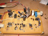
Here's a snapshot of the board
The inductance is 27uH spec'd at 1 KHz (per data sheet).
Here's a snapshot of the board
Attachments
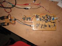
this is a closeup of the main board, component side. Most of the main stuff is in the upper 1/2 of the card. The lower right half has the feedback network while the lower right half is my sorry attempt at a preamp
You can see the inductor clearly in this picture.
How do you like my heat sink! Originally there were separate aluminum heat sinks that looked more traditional. During debug, I was having trouble with the FET's and though they needed to be thermally connected so I used a small piece of aluminum. For now, they stay cool.
Attachments
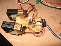
This is the sine wave generator. Looks a little like star ship enterprise (if you squint a little and swig some sambucca, that is). The circuit can generate any frequency from about 100Hz up past audio frequency. Output is variable too. With batteries, the output is fully floating - which I liked.
Attachments
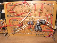
last shot for now is the under belly of the main circuit board. Most of the wiring is here. I used solder wick for buses.
Notice the large caps on the bottom. During debug it appeared that the rail decoupling was a problem so I needed to add more capacitance. No room on top for a good layout, so they wound up on the bottom instead.
Notice the large caps on the bottom. During debug it appeared that the rail decoupling was a problem so I needed to add more capacitance. No room on top for a good layout, so they wound up on the bottom instead.
Attachments
gearheadgene said:The inductance is 27uH spec'd at 1 KHz (per datasheet).
That may indeed be the reason the core is getting hot. You need to be very wary when manufacturers only specify their cores at very low frequencies. I certainly wouldn't use any inductor that is only specified at 1kHz in a class d amp that switches at 400kHz.
Looking at other inductors from JW Miller, they have "low loss core" styles too. Those are spec'd at much higher frequencies. I've fired off an email to the manufacturer for some recomendations.
Any feelings about using shielded inductors instead of toroidal? The EMI benefit seems worthwhile.
Any feelings about using shielded inductors instead of toroidal? The EMI benefit seems worthwhile.
I've used these inductors previously, but at frequencies not much higher than 100 Khz.
Although the data sheet does not mention the core material specifically, or its operating frequency, there are two key words in the datasheet: "Low Cost".
This would essentially mean a low grade core, which would have excessive losses at the frequencies you are working with.
The same vendor offers the same 2200-series of toroids, in a low core-loss format.
Check out the following link: http://www.bourns.com/pdfs/2200ll_series.pdf
fyi - I played some audio through the amp for the first time tonight. It sounds pretty good! Nothing is optimized yet. The audio source is an MP3 player that really doesn't have enough zip to drive the amp to full output - yet it's pretty loud.
One thing that stands out immediately is that there is some pretty obvious high frequency hiss coming from the mid-range and tweeter. Even with the input removed, the amp is generating this noise. Can anyone comment on acceptable or typical noise floor?
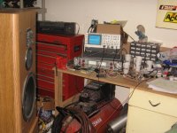
I attached a picture of the lab/garage with the amp running!
One thing that stands out immediately is that there is some pretty obvious high frequency hiss coming from the mid-range and tweeter. Even with the input removed, the amp is generating this noise. Can anyone comment on acceptable or typical noise floor?
I attached a picture of the lab/garage
with the amp running!Attachments
The core material is iron powder and the color marking is yellow-white(seen on the second picture, probably T106-26 type).Its not intended to work at these frequencies(400kHz in your project).Those are used in SMPS at some 20...25kHz.But they will do OK if u use them in rail voltage filters.In my last project I tried T106-2(color marking red or red-dark green).In my project they don´t even get warm.Here is some pretty cool calculator.
http://www.66pacific.com/calculators/toroid_calc.aspx
BTW The original schematic is not mine
http://www.66pacific.com/calculators/toroid_calc.aspx
BTW The original schematic is not mine
- Status
- This old topic is closed. If you want to reopen this topic, contact a moderator using the "Report Post" button.
- Home
- Amplifiers
- Class D
- typical unwanted amp byproducts