I have built a power amp with UCD180 module end of 2006 and listen to it nearly everyday. I'm quite satisfied with it. Then I attempted to built a UCD amp from the Philips application notes by referring to the thread http://www.diyaudio.com/forums/showthread.php?s=&threadid=85389. I built one channel UCD on a breadboard and seem to be working good. Then I make some PCBs and have built several modules. But unfortunately I got stability problem. I haven't found the reason why yet but I do believe the problem is with the inductor.
After reading a thread in Vendor Bazaar forum about an MHz Class-D power amp module, I decided to have a try a Class-D amp with higher switching frequency. The modules MCD-255 are not cheap at all although it is come from China.
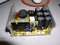
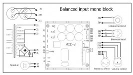
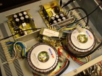
As a DIYer, I'm quite confused that no instruction manual was enclosed in the package. I remembered that the designer had posted the connection diagram. So, I get the diagram there and start building the amp. I'm also frustrated that the some part of the circuit is sealed as shown in the attached pictures. Considering the condition of soldering, the module seems to be soldered by hand. The PCB has not been cleaned as well.
The documentation from the manufacturer is almost NONE, so I start this thread to share with other builders.
Following are my questions,
1. What is the input power voltage range? I got two 24V AC transformers currently for testing. Before any attempt to connect a speaker, I wanted to measure the switching residue at the output with a 100MHz scope first. But I failed. I can hear two relay clicks when it was powered up. I cannot measure any switching residue at the output. It seems the amp was not yet started up or the protection circuit was in action.
2. The module comes with a built-in pre-amp, which can be bypassed. So, what are the input impedances and the gains of the pre-amp and the power stage?
3. Is it appropriate to enclose the inductor with a shrink-wrap jacket? Will the inductor get hot during operation?
4. Is the input DC or AC Coupled?
Thanks in advance.
After reading a thread in Vendor Bazaar forum about an MHz Class-D power amp module, I decided to have a try a Class-D amp with higher switching frequency. The modules MCD-255 are not cheap at all although it is come from China.
As a DIYer, I'm quite confused that no instruction manual was enclosed in the package. I remembered that the designer had posted the connection diagram. So, I get the diagram there and start building the amp. I'm also frustrated that the some part of the circuit is sealed as shown in the attached pictures. Considering the condition of soldering, the module seems to be soldered by hand. The PCB has not been cleaned as well.
The documentation from the manufacturer is almost NONE, so I start this thread to share with other builders.
Following are my questions,
1. What is the input power voltage range? I got two 24V AC transformers currently for testing. Before any attempt to connect a speaker, I wanted to measure the switching residue at the output with a 100MHz scope first. But I failed. I can hear two relay clicks when it was powered up. I cannot measure any switching residue at the output. It seems the amp was not yet started up or the protection circuit was in action.
2. The module comes with a built-in pre-amp, which can be bypassed. So, what are the input impedances and the gains of the pre-amp and the power stage?
3. Is it appropriate to enclose the inductor with a shrink-wrap jacket? Will the inductor get hot during operation?
4. Is the input DC or AC Coupled?
Thanks in advance.
Attachments
hello gogowatch
happy new year
1.about the data sheet:
you are the very first user of mcd-255(ver 6)
and we are doing with the paper work.
so we promise that we will post the pdf at this two days.
sorry for the delay.
2.
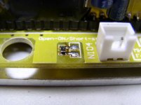
the black one is the protection of mcd-modules.
and the res is the dead time turner,
we test every pcs of mcd modules before it go out to users.
and we will turn the dead time by hand for every pcs to make it run at his best .
sorry for the "not clean well ", i will check the product line to make it better.
thank you for your post
then i will answer your questions
rg
fumac
happy new year
1.about the data sheet:
you are the very first user of mcd-255(ver 6)
and we are doing with the paper work.
so we promise that we will post the pdf at this two days.
sorry for the delay.
2.
the black one is the protection of mcd-modules.
and the res is the dead time turner,
we test every pcs of mcd modules before it go out to users.
and we will turn the dead time by hand for every pcs to make it run at his best .
sorry for the "not clean well ", i will check the product line to make it better.
thank you for your post
then i will answer your questions
rg
fumac
question 1
1. What is the input power voltage range? I got two 24V AC transformers currently for testing. Before any attempt to connect a speaker, I wanted to measure the switching residue at the output with a 100MHz scope first. But I failed. I can hear two relay clicks when it was powered up. I cannot measure any switching residue at the output. It seems the amp was not yet started up or the protection circuit was in action.
------------------------------
mcd-255 need a +/-45V DC supply for 250w.
the max voltage is +/-49V dc (35V AC, will protection at about 50V),
but the input voltage of 230v(or 110v)sometimes will up to 110% or 120%.
so we need a voltage under 49v-6v=43VDC(30V AC)
===so 30-0-30v (AC) is a best choose.===
24V AC is too low, sometimes cant power up.
so this voltage is not the best choise of
so the best is raise the voltage.
but you can heard the "click" of relays , that meaning it is running.
i'm sure it is running.
because the speaker protection of mcd is checking the pwm signal ,
if working ok the relays will turn on. if not , the relays will turn off.
so if you heard one sound of "click", this is meaning : mcd is running .
mcd just output very low switching residue voltage(mV level),
not like others(V level).
so u need to turn your osc scope to lower range.
perhaps you can look at it .
also u cant just hearing the speaker to know about it is on/off.
because mcd output a very low noise.
rg
fumac
the built-in pre-amp is working at +/-15v regulator.
Gain : 30.5db, (33.6x)
before pot (input stage): 6db(2x)
after pot(buffer): 9.5db(3x)
power stage :15db(5.6x)
if u input a 1v signal then you can get a 33.6v at the output pin.
so you can use most of music source .also low level output source.
input impedance :
pre-amp :15k (unbalance),30k (balanced)
buffer:18k
power stage: 6k
because mcd have a high input impedance,
so you can use a tube pre-amp to replace the pre-amp.
or even replace the buffer.
4. Is the input DC or AC Coupled?
pre-amp input is DC Coupled
pre-amp to buffer is DC Coupled too
buffer to power stage is AC Coupled (20uf cap)
question 3
3. Is it appropriate to enclose the inductor with a shrink-wrap jacket? Will the inductor get hot during operation?
because the good design of mcd-255, the inductor just get a mini hot during operation.
so we enclose the inductor with a shrink-wrap jacket,
this will make the value of inductor more Stability
enjoin your new amp
rg
fumac
Thanks for your reply, Fumac.
I have just made one module start running. You guess what I've done wrong? .... I haven't supply the DC15V. I just thought the DC15V is used for the pre-amp circuit that I don't want to use at the moment. After I supplied the DC15V, I =got a single relay click, instead of two previously. When I power it down, I got another relay click. That's more reasonable. Does the module need high quality DC15V power supply?
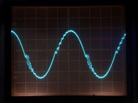
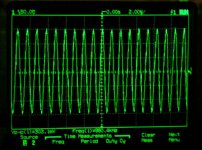
I haven't got all the components to build a complete amp. So I did some measurements before I go ahead. Attached is switching residue with power stage input shorted to ground and no load connected at speaker output. Scales are 0.2us/div and 50mV/div. It shows a ptp 220mV residue and switching frequency ~900KHz. The trace shows some high order frequencies ripples. Is that normal?
Regards,
I have just made one module start running. You guess what I've done wrong? .... I haven't supply the DC15V. I just thought the DC15V is used for the pre-amp circuit that I don't want to use at the moment. After I supplied the DC15V, I =got a single relay click, instead of two previously. When I power it down, I got another relay click. That's more reasonable. Does the module need high quality DC15V power supply?
I haven't got all the components to build a complete amp. So I did some measurements before I go ahead. Attached is switching residue with power stage input shorted to ground and no load connected at speaker output. Scales are 0.2us/div and 50mV/div. It shows a ptp 220mV residue and switching frequency ~900KHz. The trace shows some high order frequencies ripples. Is that normal?
Regards,
Attachments
gogowatch said:Thanks for your reply, Fumac.
I have just made one module start running. You guess what I've done wrong? .... I haven't supply the DC15V. I just thought the DC15V is used for the pre-amp circuit that I don't want to use at the moment. After I supplied the DC15V, I =got a single relay click, instead of two previously. When I power it down, I got another relay click. That's more reasonable. Does the module need high quality DC15V power supply?
I haven't got all the components to build a complete amp. So I did some measurements before I go ahead. Attached is switching residue with power stage input shorted to ground and no load connected at speaker output. Scales are 0.2us/div and 50mV/div. It shows a ptp 220mV residue and switching frequency ~900KHz. The trace shows some high order frequencies ripples. Is that normal?
Regards,
cheers and happy new year
i like to hear about your mcd-255 is running
")
the 15V sub power is for control circle and low side driver
there are a 12v regulator inside mcd-255.
so not need to add a extension regulator for mcd-255
and the caps of the sub-power must be under 1000uf.
if large than it , it will be make err to the soft-star circle.
about the PWM frequency, the frequency is depend on the power rail ,if you use higher rail, (+/-43v), then you can get the higher pwm frequency, also when the mcd-255 warm up,the frequency will also goto 1mhz(+/-60K)
and about the 220mV residue , when the pwm frequency higher, the residue will be lower.
you can test about your another low frequency class-d amp, then you will find our residue is very very lower than others
another side, we can make the residueunder 10mV, but this will make the frequency respond jst up to 50kHz(-3db), but we have test about it , up to 150khz(-3db) is quite better than the 50k.
so take it easy
rg
fumac
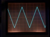
10V/div=60V?gogowatch said:One more trace. This one is from the power amp output pin without speaker loading with triangular signal at power stage input pins. Scales are 0.2ms and 10v/div.
gogowatch said:Thanks for your reply, Fumac.
I haven't got all the components to build a complete amp. So I did some measurements before I go ahead. Attached is switching residue with power stage input shorted to ground and no load connected at speaker output. Scales are 0.2us/div and 50mV/div. It shows a ptp 220mV residue and switching frequency ~900KHz. The trace shows some high order frequencies ripples. Is that normal?
Regards,
The "high order" frequencies are plain EMI (electromagnetic interference) and are the result of bad engineering and poor PCB layout. They should not be there. This is particularly true if the amplifier was idle when you took this picture, because the RF "ringing" will become much worse under load when substantial current is being supplied to the speaker.
You can take a look at the carrier residuals of your original UcD modules (good engineering) and you will see a clear difference in waveform quality. A good class D module should not exhibit any RF ringing at the speaker output (or at any input/output connector) because wires are nice antennas.
This article is worth reading too, if you have not read it already:
http://www.audioholics.com/educatio...ics/switching-amplifier-class-d-basics-page-2
Eva said:
The "high order" frequencies are plain EMI (electromagnetic interference) and are the result of bad engineering and poor PCB layout. They should not be there. This is particularly true if the amplifier was idle when you took this picture, because the RF "ringing" will become much worse under load when substantial current is being supplied to the speaker.
You can take a look at the carrier residuals of your original UcD modules (good engineering) and you will see a clear difference in waveform quality. A good class D module should not exhibit any RF ringing at the speaker output (or at any input/output connector) because wires are nice antennas.
This article is worth reading too, if you have not read it already:
http://www.audioholics.com/educatio...ics/switching-amplifier-class-d-basics-page-2
hi eva happy new year
yes your thinking is right,
but perhaps you just told others a part of truth
most of testing ringing is come from method of measurement
yes, most of diy project.
measurement technolege is very complex
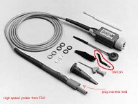
i think the ringing is came from the GDN pin of probe too long
perhaps gogowatch can post a pic of the test probe
and i show you a picture
eva if you like , we can post a new topic :measurement of class-d amp.
perhaps can help other ture
rg
fumac
Attachments
soongsc said:I think it would be interesting to see difference between a resistive load and a tweeter driver type load.
Soongsc,
I don't have standalone tweeter driver on hand. Is it useful to test driving an ordinary two ways speaker?
Cheers,
A proper design does not ring, particularly not above 10Mhz because radiation becomes much easier. It may exhibit just one or two damped oscillation cycles, but never a dozen cycles with very slow decay. The net amount of EMI radiated is proportional to the number of cycles
Of course, if some part of the circuit is ringing above 10Mhz, you will notice it with oscilloscope probes no matter where you connect them because part of this ringing will be common-mode (circuit ground will be no longer RF ground!!) and part of it will be just radiated and picked up by the probes.
The only remedy for this is to kill the ringing, which is achieved by removing as much parasitistic RLC systems as possible and ensuring that the rest of unavoidable RLC systems in the power path are reasonably damped. This is some kind of obscure RF engineering
BTW: Now you are free to continue telling everybody that my PCB layouts are bad, but then again, I get no ringing at the output, I "shape" my EMI to appear as clean pulses
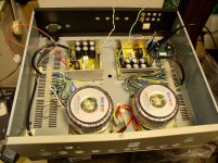
gogowatch said:Fumac,
Attached the image shows how I arrange the probe similar to the one when I did the residue measurement last time.
Cheers,
good job gogowatch
your installation design is quite good,
samll signal and large singal is Separated
and you use two transformer for two channel
this is quite good for low cross talk and power output
also you can add more caps , it will be very good for high dynamic
and can you talk about the sound feeling of it
perhaps many people like to know that
you are the only one have both mcd and ucd,
btw, the osc probe is alittle longer, show you a pic about a high frequency osc probe
a right Test Method will get the Accurate results
and can you tell me the length of your gan pin
rg
fumac
Attachments
- Status
- This old topic is closed. If you want to reopen this topic, contact a moderator using the "Report Post" button.
- Home
- Amplifiers
- Class D
- MHz Class-D MCD-255 building question