lumanauw said:Hi, Fumac,
For achieving Mhz selfoscilation, is it more about the mosfet choice or special feedback topology or comparator gain, or driver speed, or what? Is there something you can share?
hello lumanauw
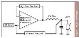
i think the most important is the block diagram
fast and low input cap mosfet,
u can take a look at this link (from eva)
http://www.diyaudio.com/forums/showthread.php?s=&threadid=112065
also need a hard driver for mosfet.
rg
fumac
Attachments
also
u can take a look at this link
http://www.diyaudio.com/forums/showthread.php?s=&threadid=101774
he is designing a driver for his 1kw d-amp
rg
fumac
u can take a look at this link
http://www.diyaudio.com/forums/showthread.php?s=&threadid=101774
he is designing a driver for his 1kw d-amp
rg
fumac
lumanauw said:Hi, Fumac,
I like that you help other members technically. In DIYaudio, we all learn something, especially technical aspect. Kind of "give and take" between members. Maybe you will also learn something from other member that will be usefull for yourself
hi lumanauw
yes u r right
i remember that i have told u about the design of ur PCB,
how a about the pcb now, perhaps u can send a email to me
thanks
fumac
Hi, Fumac,
PCB? No, I haven't draw the PCB yet. The last one really a mess Thanks for your tips. I still experimented on bread-board.
I wanted to ask you about my Mhz modulation. My basic thinking is simple. The selfoscilation frequency seems always appropriate to residual voltage. The less residual voltage, it means higher selfoscilating frequency.
This is what I tought. If input differential needs 1V2 (p-p) to activate the state change (from "on" to "off"), what if we use 2 inverting stages (the comparator and the output stage is inverting), and then since the comparator is inverting, we feed back some of the signal back to the input. So it will, say provide 0V9 (p-p) and the output only have to provide 0V3. 0V3 residual means very high selfoscilation frequency.
I haven't draw anything yet, but this schematic (got it from here) seems to be able to represent my idea.
If you look the output stage (common sources), it is inverting output stage. "on" from the input of totem pole (bcw66/68) means "off" at the output node.
My experiment is like this, I put 47k resistor from pin1 to pin 3 of LM393. I got 1Mhz selfoscilation with IRF530/9530 with this method, but still very dirty oscilation.
What do you think about my method for achieving 1Mhz selfoscilation?
PCB? No, I haven't draw the PCB yet. The last one really a mess
Thanks for your tips. I still experimented on bread-board.I wanted to ask you about my Mhz modulation. My basic thinking is simple. The selfoscilation frequency seems always appropriate to residual voltage. The less residual voltage, it means higher selfoscilating frequency.
This is what I tought. If input differential needs 1V2 (p-p) to activate the state change (from "on" to "off"), what if we use 2 inverting stages (the comparator and the output stage is inverting), and then since the comparator is inverting, we feed back some of the signal back to the input. So it will, say provide 0V9 (p-p) and the output only have to provide 0V3. 0V3 residual means very high selfoscilation frequency.
I haven't draw anything yet, but this schematic (got it from here) seems to be able to represent my idea.
If you look the output stage (common sources), it is inverting output stage. "on" from the input of totem pole (bcw66/68) means "off" at the output node.
My experiment is like this, I put 47k resistor from pin1 to pin 3 of LM393. I got 1Mhz selfoscilation with IRF530/9530 with this method, but still very dirty oscilation.
What do you think about my method for achieving 1Mhz selfoscilation?
Attachments
lumanauw said:My experiment is like this, I put 47k resistor from pin1 to pin 3 of LM393. I got 1Mhz selfoscilation with IRF530/9530 with this method, but still very dirty oscilation.
Hi David,
Your driver arrangement is very crude and weak and also suffer when subjected to extreme of dutycycles 0-100%
lumanauw said:Hi, Fumac,
I still experimented on bread-board.
u post the pic is not use our mcd block diagram
just like ucd
we use two paths after and before the output filter
one for osc, one for af feelback
i have heard about a saying from westen:
amp like an amp, osc like an osc.
our two paths r one for amp , one for osc.
dont use bread-board to make a damp
is not a rightway
pcb is the 70%important of a D-AMP
best rg
fumac
Hi, Kanwar,
It is the same output stage used in Fredo's Behringer mixer, the same as output stage used in Zetex classD (look at datasheet of ZXCD1000), similiar to JohnW built. I also have no experience with this kind of output stage. It's just very simple to construct.
Do you have idea how to make it (a little) better? Will using 2 totem poles (1 for high 100nF and 1 for low 100nF) can help? Or making it cascaded totem pole (inverting driver, like in Labgruppen TD driver)?
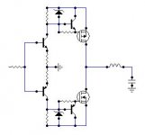
The drive circuit used by David in post #24 is the same one as used in a famous AN by Motorola.
I once ( i.e. 15 years ago) used a similar one but added a parallel DC path so that it is capable of duty cycles form 0 to 100 %. I once posted the schematic on this forum.
Regards
Charles
I once ( i.e. 15 years ago) used a similar one but added a parallel DC path so that it is capable of duty cycles form 0 to 100 %. I once posted the schematic on this forum.
Regards
Charles
lumanauw said:That's quick, thanks
I assume you have experimented with this kind of output stage before? Good enough?
I have tried that topology in 100W amp with success
lumanauw said:Hi, Kanwar,
Will it be better if we replace resistor between B-E of the mosfet driver with 1N4148, like UCD-clone mosfet drive?
You can add schottky IN5819 also.....
Hi, Fumac,
This morning, I just (re)read AES paper 5503 May 10-13 2002 Munich about Mueta amp. In page 3 it is stated :
This morning, I just (re)read AES paper 5503 May 10-13 2002 Munich about Mueta amp. In page 3 it is stated :
How real is this "excessive dead time errors" in Mhz frequency classD modulation?A typical value for audio application is 300 to 400khz which is sufficiently high for high fidelity, while still low enough to prevent exessive dead time errors
lumanauw said:Hi, Fumac,
This morning, I just (re)read AES paper 5503 May 10-13 2002 Munich about Mueta amp. In page 3 it is stated :
A typical value for audio application is 300 to 400khz which is sufficiently high for high fidelity, while still low enough to prevent exessive dead time errors
How real is this "excessive dead time errors" in Mhz frequency classD modulation?
hi lumanauw
good question !
dead time will cause Distortion, i cant tell u the dead time about MCD, but i can tell u the Distortion of MCD-6.
0.0035% at 1W 1k
u can get it from the picture of the 1st post of this title.
the Distortion is good enough ?
no, our thinking is just not bad.
u can download some pdf of other class-D that running at 300~400k,
then u will find the answer
in the HI end audio , nothing is enough!
some one had told us , 44k sample rate is good enough for CD, but now we can buy a 192khz sample rate CDplayer. fun
perhaps after years, HHHDCD will say hello to us , who knows it .
i have told u , running at 1mhz can give us :
very low phase shift at treble. <10DG at 20k
very width frequency respond,0~150kHz(-3db)
very low pwm idel output : 50mV(rms)
or u can select running at 300k
high phase shift at treble: >60DG at 20k
nomal frequency respond: 0~30kHz(-3db)
high pwm idle output: 0.8V~1.4V(peak) or higher and higher!
(one of class-d amp give u a 3~6V pwm idle votage at output pin,
i think he found : if he turn the pwm idle votage at a low level ,the phase shift is too large )
u cant balance all this at just 300~400k
"A typical value for audio application is 300 to 400khz which is sufficiently high for high fidelity, while still low enough to prevent exessive dead time errors "
-------------
another saying is:
if we cant get the low Distortion , we just can slow down the speed,
then the large DT will cause the Distortion not very high.
but dont forget , in hiend audio, not just Distortion
we do also care about : frequency respond, phase shift,pwm noise, an others.
why not goto 1mhz and find a way to make the Distortion lower.
diffrent thinking will give us diffrent resuit.
we r going to higher frequency now .
and we will never have a product lower than 900khz.
rg
fumac
So you are essentially getting similar or worse THD figures than UcD but you are switching at 1Mhz while UcD is switching at 250Khz most of the time.
Given how advanced is the devlopment of your product, it may be a bit late to say this, but when you increase switching frequency, non-linearity increases at a similar rate than error amplifier gain margin. In other words, all the extra feedback gain that is allowed by switching at 1Mhz is employed to correct the extra distortion due to 1Mhz switching. The impact on THD of dead-time and comparator skew time errors is roughly proportional to switching frequency.
The only two advantages are a higher bandwidth that nobody needs because we are completely unable to hear stuff above 30Khz (not to mention at 200Khz) and a very low carrier residual that forces you to get part of your feedback signal before the output filter for proper oscillation, resulting in increased output impedance and THD at higher frequencies and bringing back the classic load-impedance dependent output filter peaking problem.
Oh, and you should study some information theory because your marketing claim that a 1Mhz carrier can produce a better 20Khz signal than a 200Khz carrier is completely false. Particularly I recommend you to study the Nyquist–Shannon sampling theorem.
The claim of increased bandwidth is also partially false, because in practice a 80Khz output filter limits the clean non slew-rate limited output to approx. 40Khz.
Definitely nothing new under the sun.
BTW: Good luck with your new potential agent.
- Status
- This old topic is closed. If you want to reopen this topic, contact a moderator using the "Report Post" button.
- Home
- Amplifiers
- Class D
- mhz switching frequency