Hi
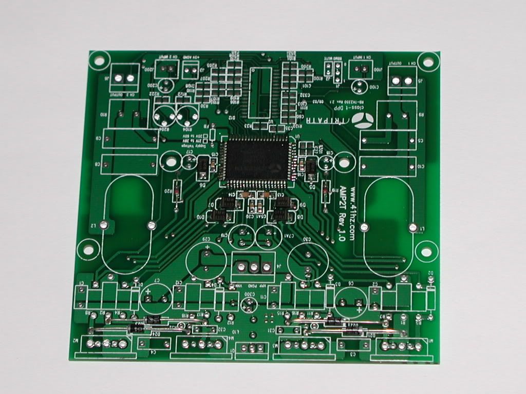
I have AMP2, which is based on tk2350 chipset. The mosfet driver is the bigger chip that needs to be cooled. For this it has soldering slug under it. Since this is under chip you can't solder it with iron so you have one or two options.
First one is to use heat transfer paste under chip and use heatsink on top of this chip, or second you have to solder that slug to pcb.
Since second one is better for cooling is not the easiest one. But I went for this one anyway in hope that it was the right thing to do.
For this you need soldering oven or hot plate or in my case standard electric oven. I first made test with some remaining pcb that wasn't useful for anything. I did what AMP2's pdf said. And this is what came out from all that.
Day 1:
To220 broken fet soldered to PCB
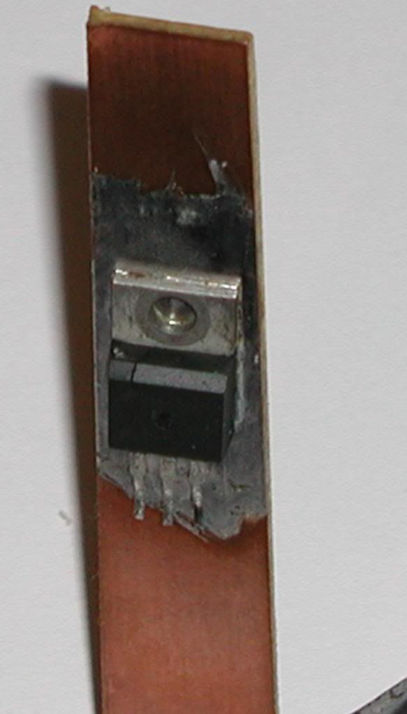
So this thing is working in normal oven too, since it can heat up a lot more then you would need. I timed this to I get some figures, to see what to expect.
After doing that it was time to go with the real thing and this is what came out this time
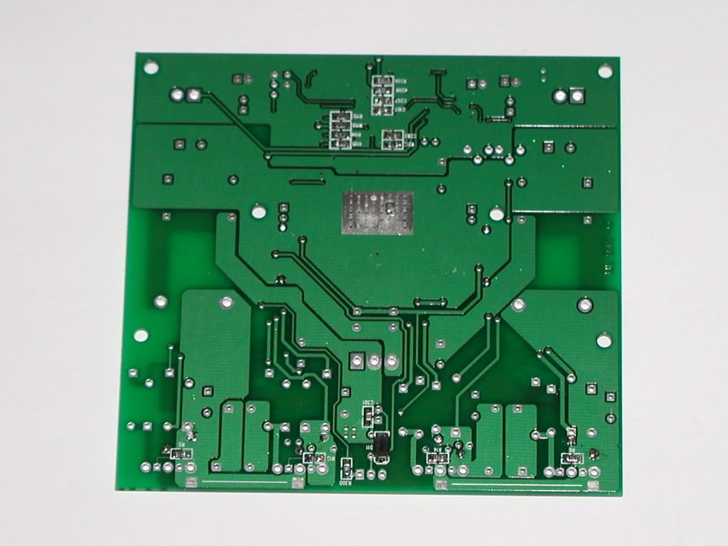
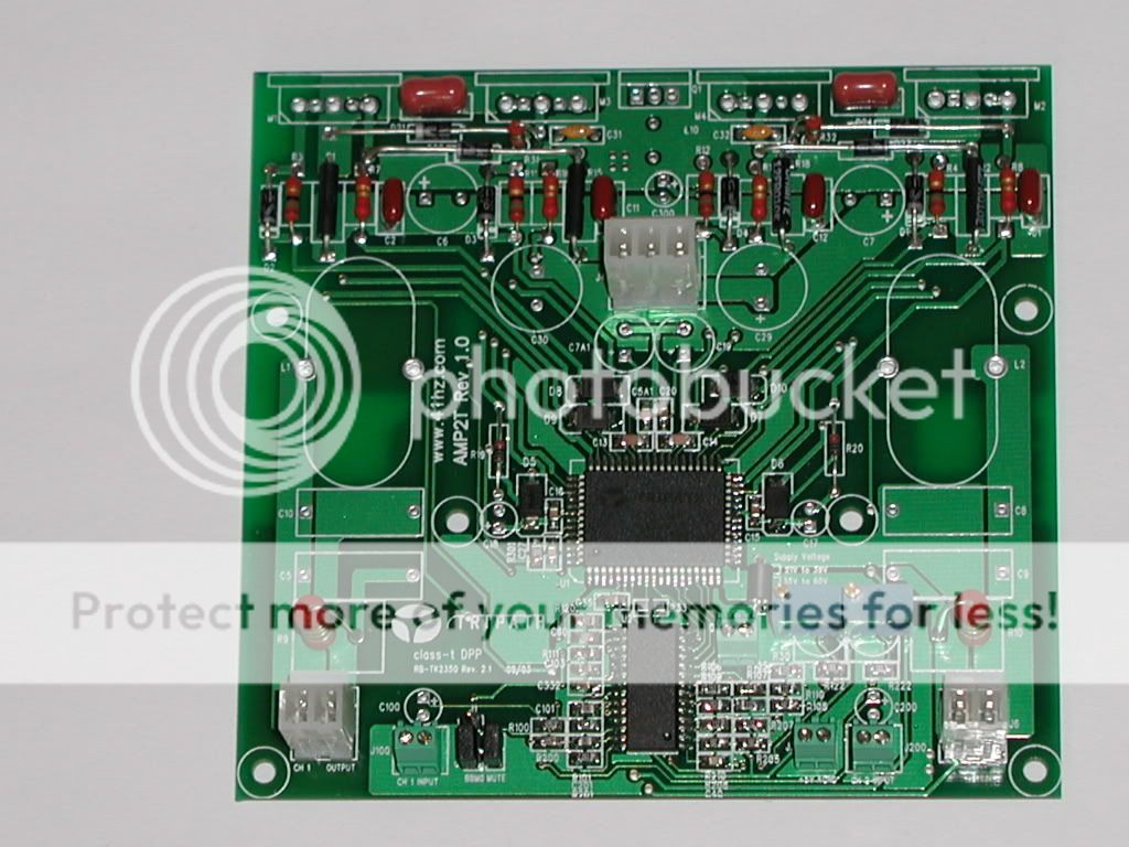
After soldering chip and all bottom SMDs and some on top
Day 2:
All SMD components are solders + output diodes
I have AMP2, which is based on tk2350 chipset. The mosfet driver is the bigger chip that needs to be cooled. For this it has soldering slug under it. Since this is under chip you can't solder it with iron so you have one or two options.
First one is to use heat transfer paste under chip and use heatsink on top of this chip, or second you have to solder that slug to pcb.
Since second one is better for cooling is not the easiest one. But I went for this one anyway in hope that it was the right thing to do.
For this you need soldering oven or hot plate or in my case standard electric oven. I first made test with some remaining pcb that wasn't useful for anything. I did what AMP2's pdf said. And this is what came out from all that.
Day 1:
To220 broken fet soldered to PCB
So this thing is working in normal oven too, since it can heat up a lot more then you would need. I timed this to I get some figures, to see what to expect.
After doing that it was time to go with the real thing and this is what came out this time
After soldering chip and all bottom SMDs and some on top
Day 2:
All SMD components are solders + output diodes

Hi
Day3: Having problems with testing resistance between Vpp and Pgnd and Vnn...
Found out that small piece of copper that came off one leg of fet when putting fets into pcb has shorted D and S of one fet. Holes are a bit too close together, so that fets would go in without little force. Now resistances are ~450k and ~660k, and 505 ohm for 5v which I think is ok
Now I must test board
Hi
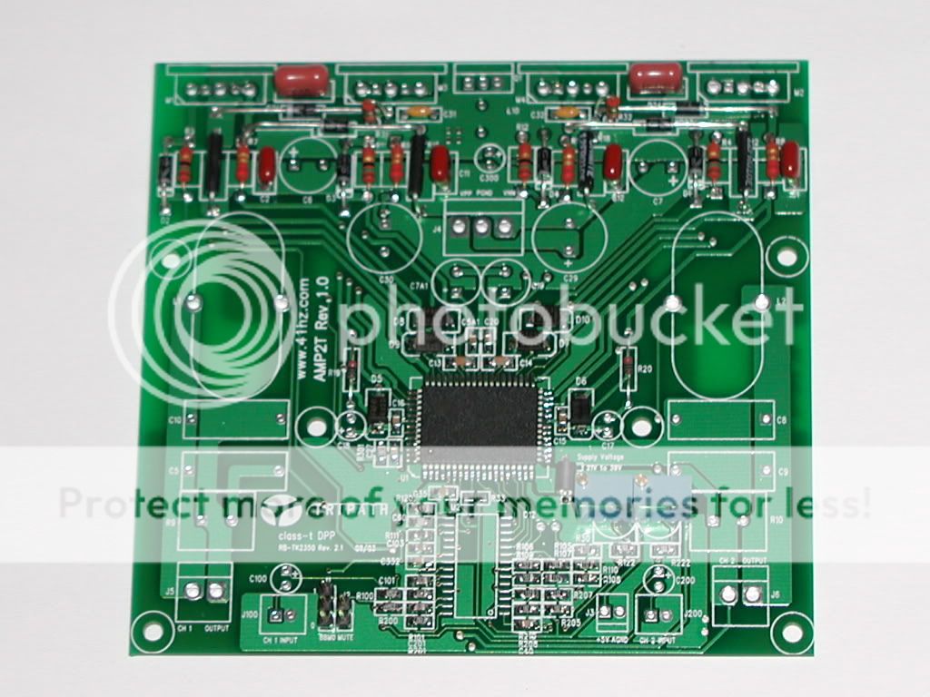
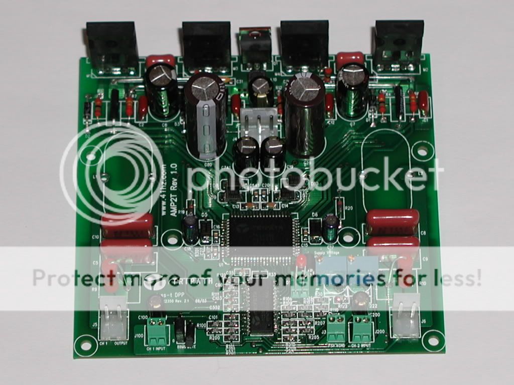
End of day3:
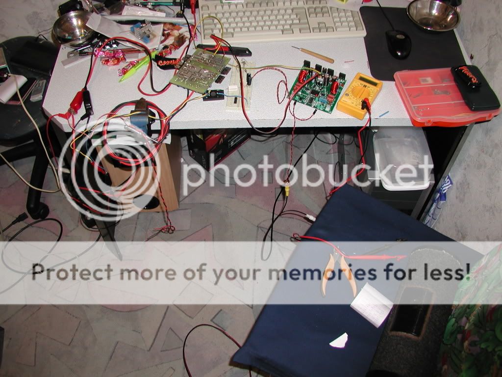
All components but toroids have been mounted, toroids will be mounted tomorrow. It is starting too look like amp now, can't wait to hear the sound, will it be that I expact it to be? Only one way to find out...
PS: with no fets and amp in mute current in Vpp rail was 0.25mA, so everything is working in this path too.
End of day3:
All components but toroids have been mounted, toroids will be mounted tomorrow. It is starting too look like amp now, can't wait to hear the sound, will it be that I expact it to be? Only one way to find out...
PS: with no fets and amp in mute current in Vpp rail was 0.25mA, so everything is working in this path too.
Hi and thanks
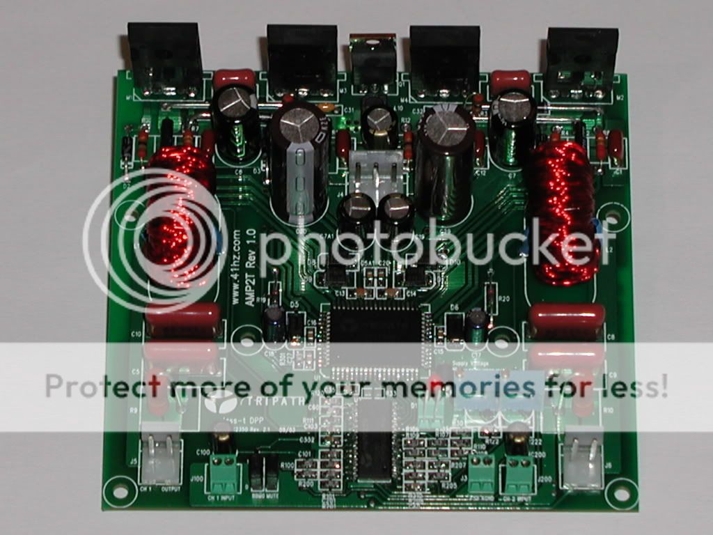
Day4, finall day:
Today toroids were first on the list... After winding them, I found out that this wires insulation wasn't coming off with lavacom (paint and wire insulation remover among other things), which meant making my own litz wire. I have some same wire size so this was great. With kit came wire with 15 stands, I used 18 so inductors should be better. This took me about 3-4 hours.
Now the testing went great also. First I put supplys ON, check that there wasn't any shorts. After that I put amp into active mode, set offset of one channel to 0.01mV and other to 0.05mV, well below 10mV that I should . Next was signal, and speaker connections... and I was ready to play some music.
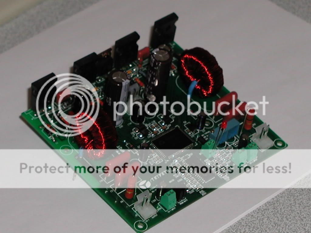
 .....
..... ......YES IT IS ALIVE
Before this amp I was listening to LM3886, but when I played music with this amp I was : This amp is just something else, so great sound that you can't even begin to describe it.
Thank's to Tripath and 41Hz for this super amp...
Some pic...
Day4, finall day:
Today toroids were first on the list... After winding them, I found out that this wires insulation wasn't coming off with lavacom (paint and wire insulation remover among other things), which meant making my own litz wire. I have some same wire size so this was great. With kit came wire with 15 stands, I used 18 so inductors should be better. This took me about 3-4 hours.
Now the testing went great also. First I put supplys ON, check that there wasn't any shorts. After that I put amp into active mode, set offset of one channel to 0.01mV and other to 0.05mV, well below 10mV that I should
. Next was signal, and speaker connections... and I was ready to play some music...... ......YES IT IS ALIVE Before this amp I was listening to LM3886, but when I played music with this amp I was
: This amp is just something else, so great sound that you can't even begin to describe it.Thank's to Tripath and 41Hz for this super amp...
Some pic...
Hi
about 2 months ago I way compliting my amp2, all I was doing was smps, trying different filters on sec, but I didn't remember to unplug supply to AMP2 board, when TK2350 blow , I looked at output voltage and it was 172v I think . So too high voltage killed it... Morale was bottom low up to now, a week ago I said "F*** it, I will throw this money for new chipset if it works or if it does not". So I had to remove driver IC, broke pins as close to IC as I could with very sharp knife, turn board upside down, took lighter and started burning IC
  ... Why the hell would I burn it? Well it had slug solderd to board, thats why! After getting it down, I resolderd new IC up, this time with paste, coz I can't use owen again. Both fets from one channel were gone too so those were fixed to.
Now it plays music again and I can't be more happy then this
about 2 months ago I way compliting my amp2, all I was doing was smps, trying different filters on sec, but I didn't remember to unplug supply to AMP2 board, when TK2350 blow
, I looked at output voltage and it was 172v I think . So too high voltage killed it... Morale was bottom low up to now, a week ago I said "F*** it, I will throw this money for new chipset if it works or if it does not". So I had to remove driver IC, broke pins as close to IC as I could with very sharp knife, turn board upside down, took lighter and started burning IC ... Why the hell would I burn it? Well it had slug solderd to board, thats why! After getting it down, I resolderd new IC up, this time with paste, coz I can't use owen again. Both fets from one channel were gone too so those were fixed to.Now it plays music again and I can't be more happy then this
Glad you were able to bring it back to life.
Did you use a lighter or a torch? When I do this I use an adjustable flame torch. The orange flame of a regular lighter will leave a bunch of black soot on the PCB.
Did you use a lighter or a torch? When I do this I use an adjustable flame torch. The orange flame of a regular lighter will leave a bunch of black soot on the PCB.
An externally hosted image should be here but it was not working when we last tested it.
Hi and thanks
ROFL, I don't want to burn hole through PCB
I used normal lighter, IC did get black from "smoke", black soot is what I mean, PCB around didn't, I had tip of the flame just under IC so max temp was used without burning IC like crazy. Propane tourch would be better, never had one...
Just to say, input ic is ok, so I have one to spare
Hi,
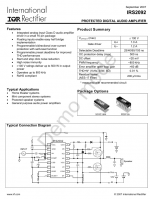
If you have further problem with the amp, you can try IRS2092. Single chip Class D Amplifier Driver from IR. Just add two external MOSFETs, a few resistors and capacitors and ..... you get a powerful class d amp with power as high as that can be handled by the MOSFETs!
If you have further problem with the amp, you can try IRS2092. Single chip Class D Amplifier Driver from IR. Just add two external MOSFETs, a few resistors and capacitors and ..... you get a powerful class d amp with power as high as that can be handled by the MOSFETs!
Attachments
Amp is finished and playing. While it looks impressive, sound is even more impressive. I am lucky I was able to buy one. It does not need any modification apart from few parts like over current and gain...that is if you would like to have diffrent settings then original, but you do that right away. It did needed repairing, but that was because of my mistakeTahmid said:Hi,
What is the present condition of the amp? The board looks impressive but is the performance as impressive?
Is it completely finished or still requires some repairing/modification?
- Status
- This old topic is closed. If you want to reopen this topic, contact a moderator using the "Report Post" button.
- Home
- Amplifiers
- Class D
- Building AMP2 from 41Hz