Hi !
I built a D amp, it sounds very nice, much better than I was expecting.
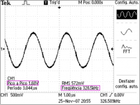
Well, althought it works fine, I can measure 1,7V peak to peak of switching waveform on the speaker output. The frequency is 325Khz.
Inductor is 22uH and capacitor is 680nF.
I don't know if it's related, but it heats considerably when IDLE, and just a little bit more when playing at full power. I was expecting it to be cold during idle period and slightly warm when playing.
Is it fine, or is my output filter faultly ?
Thank you very much !
Best Regards
I built a D amp, it sounds very nice, much better than I was expecting.
Well, althought it works fine, I can measure 1,7V peak to peak of switching waveform on the speaker output. The frequency is 325Khz.
Inductor is 22uH and capacitor is 680nF.
I don't know if it's related, but it heats considerably when IDLE, and just a little bit more when playing at full power. I was expecting it to be cold during idle period and slightly warm when playing.
Is it fine, or is my output filter faultly ?
Thank you very much !
Best Regards
-_nando-_ said:Well, althought it works fine, I can measure 1,7V peak to peak of switching waveform on the speaker output. The frequency is 325Khz.
Inductor is 22uH and capacitor is 680nF.
I don't know if it's related, but it heats considerably when IDLE, and just a little bit more when playing at full power. I was expecting it to be cold during idle period and slightly warm when playing.
Is it fine, or is my output filter faultly ?
Thank you very much !
Best Regards
You cannot eliminate carrier waveform completely, only thing you can do is attenuate it using filter.......so the 1.7pk residual is just fine.....nothing to worry.....
regarding heating at idle i think its a more shoot through or low deadtime problem......post some waveforms.....of output
If you make selfoscilating UCD style, this residual is needed to keep the amp working. If you eliminate this, the amp won't work at all. But if you make classD with feedback before LC, its a different story.
I've tried to eliminate this residual by using another LC (after feedback point, that makes it 2 sets of LC), the residual is almost 0.
I've tried to eliminate this residual by using another LC (after feedback point, that makes it 2 sets of LC), the residual is almost 0.
")
Hi, Nando,
I've never built this IC, so I don't know about it.
From page 6 of the datasheet, it seems you better try to get about 500khz frequency (by adjusting Rosc?)
From page 10 schematic, the LC used is 100uH+390nF. You use 22uH+680nF. Could the problem is because of these 2 factors?
I've never built this IC, so I don't know about it.
From page 6 of the datasheet, it seems you better try to get about 500khz frequency (by adjusting Rosc?)
From page 10 schematic, the LC used is 100uH+390nF. You use 22uH+680nF. Could the problem is because of these 2 factors?
Re: Re: Carrier frequency remains after the output filter
This is a little off topic, but there is a way to all but eliminate the residual without filtering. Instead of connecting the speaker to ground you can connect it to the output of a noninverting amplifier/buffer whose input signal is the residual. Since the residual voltage is relatively low a class ab amp with low rail voltages can be used so there is minimal power dissipation from this extra output stage. I believe I saw this method shown in a patent that was linked to or described somewhere in this forum. It was a while ago but it is an interesting way to solve the problem (even though it really isn't a problem).
Workhorse said:You cannot eliminate carrier waveform completely, only thing you can do is attenuate it using filter
This is a little off topic, but there is a way to all but eliminate the residual without filtering. Instead of connecting the speaker to ground you can connect it to the output of a noninverting amplifier/buffer whose input signal is the residual. Since the residual voltage is relatively low a class ab amp with low rail voltages can be used so there is minimal power dissipation from this extra output stage. I believe I saw this method shown in a patent that was linked to or described somewhere in this forum. It was a while ago but it is an interesting way to solve the problem (even though it really isn't a problem).
The residual is not a problem at all for speakers. Furthermore, residual cancellation methods (also class BD modulation) actually change the differential-mode residual into a more harmful common-mode thus resulting higher EMI.
In my opinion, the ideal approach would produce equal residuals in both output speaker wires, but with inverse polarity (for zero common mode component). A straight full bridge (no BD modulation) achieves this.
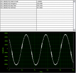
BTW: Nando, I think that your waveforms actually contain substantial RF ringing after each switching transient that is almost hidden because it seems to be outside the frequency response of your oscilloscope or measurement. Note how the carrier residual becomes noisy for a long time after each zero crossing (when switching takes place). If this RF is actually there, you will have still a lot of work to do to get a good amplifier...
In my opinion, the ideal approach would produce equal residuals in both output speaker wires, but with inverse polarity (for zero common mode component). A straight full bridge (no BD modulation) achieves this.
BTW: Nando, I think that your waveforms actually contain substantial RF ringing after each switching transient that is almost hidden because it seems to be outside the frequency response of your oscilloscope or measurement. Note how the carrier residual becomes noisy for a long time after each zero crossing (when switching takes place). If this RF is actually there, you will have still a lot of work to do to get a good amplifier...
Hi Eva !
This is a very experimental through hole approach, the layout isn't that good and... Maybe is this RF is making my amp oscillate and get warmer than it should ?
There's absolutelly nothing special with the power supply, probably the noise is coming from there...
All the 100nF bypass caps are placed as close as possible of the pins, and connected directly to the massive ground. Actually its out of the layout and it is placed manually bellow the chipamp. They are polyester types, 63v epcos (the blue package). Would ceramic caps be better?
lumanauw said:Hi, Nando,
I've never built this IC, so I don't know about it.
From page 6 of the datasheet, it seems you better try to get about 500khz frequency (by adjusting Rosc?)
From page 10 schematic, the LC used is 100uH+390nF. You use 22uH+680nF. Could the problem is because of these 2 factors?
You are reading a very old datasheet. Look at this:
http://www.nxp.com/acrobat/datasheets/TDA8920B_2.pdf
For carrier-based PWM (i.e. non self-oscillating) amps output-filters with zeroes can be used. I once used a Cauer filter and achieved a carrier-suppression of 83 dB.
But as some have already mentioned - it is not necessary to suppress it that much at all.
Twenty years ago there were rumours that any residual had to be removed as much as possible in order to achieve good audio quality.
We now know that quite the contrary is true: Do only suppress the carrier as much as necessary in order to allow the use of a filter with less influence at audio frequencies.
Regards
Charles
- Status
- This old topic is closed. If you want to reopen this topic, contact a moderator using the "Report Post" button.
- Home
- Amplifiers
- Class D
- Carrier frequency remains after the output filter