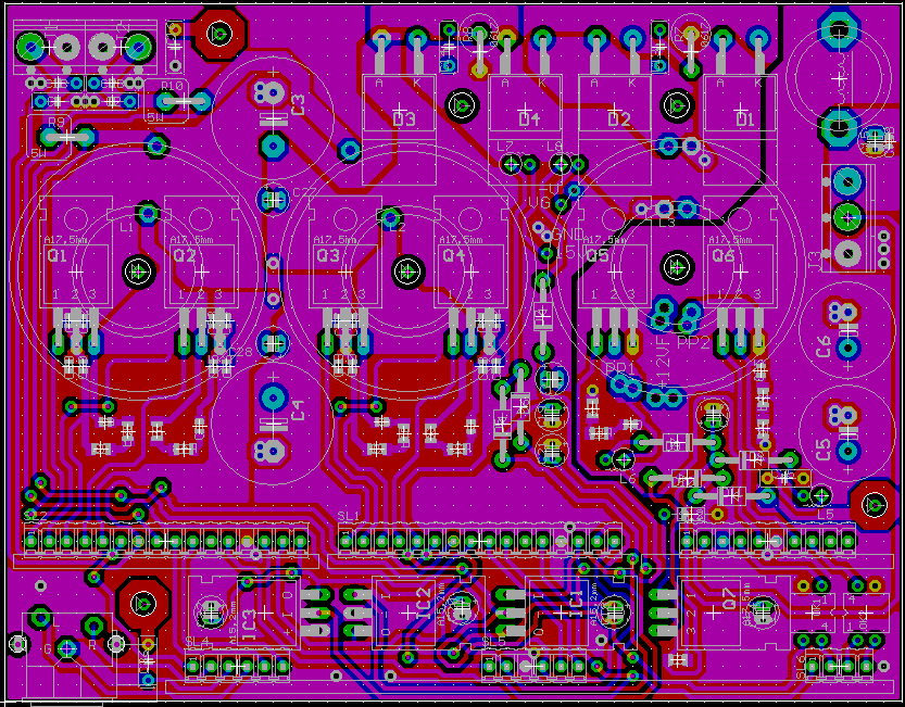
I'm also working on this project. The board layouts are almost finished...
Main board:

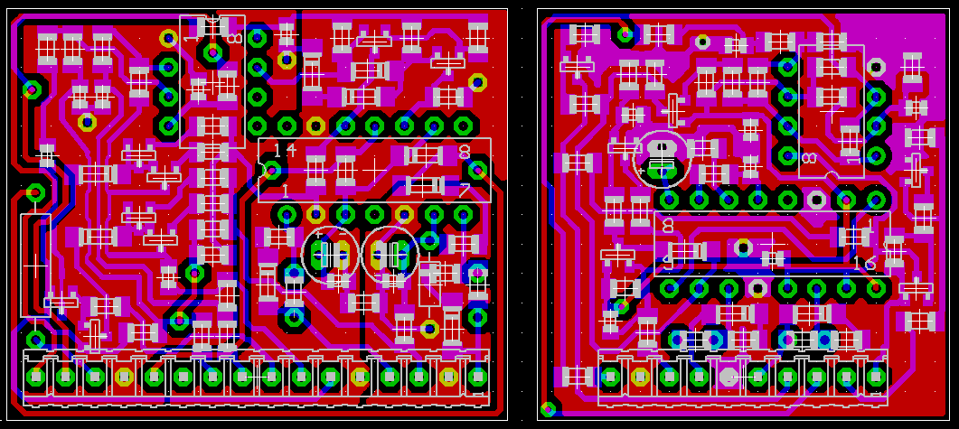
Class D amp boards (left) and PSU drive board (right):

This is essentially an UcD-based self-oscillating stereo amplifier with a built-in unregulated push-pull power supply. It's also the first time that I'm going to use SMD.
The power supply is intentionally weak because I wanted a very compact amplifier and class D circuits actually draw very little current when playing music so a huge PSU is not required at all. Main board measures just 127mm by 100mm and total height is going to be 50mm including heatsink and case. Heatsink is going to be made of thick aluminium sheet because of the small amount of heat produced.
The power supply control board includes under-voltage and over-heating shutdown logic. It also includes a "fault" latching shutdown mode for output DC protection (not yet implemented). The amplifier boards include true self-oscillating current limiting. There is a third pre-amplifier board that is not yet designed and that is supposed to contain input filters, gain/volume control and the DC protection.
More to come...
Main board:

Class D amp boards (left) and PSU drive board (right):

This is essentially an UcD-based self-oscillating stereo amplifier with a built-in unregulated push-pull power supply. It's also the first time that I'm going to use SMD.
The power supply is intentionally weak because I wanted a very compact amplifier and class D circuits actually draw very little current when playing music so a huge PSU is not required at all. Main board measures just 127mm by 100mm and total height is going to be 50mm including heatsink and case. Heatsink is going to be made of thick aluminium sheet because of the small amount of heat produced.
The power supply control board includes under-voltage and over-heating shutdown logic. It also includes a "fault" latching shutdown mode for output DC protection (not yet implemented). The amplifier boards include true self-oscillating current limiting. There is a third pre-amplifier board that is not yet designed and that is supposed to contain input filters, gain/volume control and the DC protection.
More to come...
Eva said:It's also the first time that I'm going to use SMD.
Waaaaa?

Nice job though.
Super EVA !
Looking forward to hear more about it...
Also working on D-AMP not ucd but crystal controlled (see my thread) D-Amp is back !
nice job you're doing in this forum !
your power supply xfrmr is driven by only 2 fets isn't it ?
isn't it a bit under rated for a 12V SMPS ?
300W of audio power means at least 350-400W power supply...so 30-35 A @12V
"300W" of full-range audio translate into 60W (or so) average power consumption on class D. Note that the push-pull MOSFETs are going to be IRFZ48V with 0.010 typ. Rds-on and the gates are going to be driven with 18V even during lo-bat conditions, so the transformer is actually going to suffer more than the MOSFETs...
In the first prototype of the 230V to 14.4V 72A power supply for car-audio shows that I built, I was using just a pair of IRFZ48V as synchronous rectifiers for 72A continuous output (50A rms on each device) and they never blew. The gates were also driven with 18V and there was a fan keeping them cool.
In the first prototype of the 230V to 14.4V 72A power supply for car-audio shows that I built, I was using just a pair of IRFZ48V as synchronous rectifiers for 72A continuous output (50A rms on each device) and they never blew. The gates were also driven with 18V and there was a fan keeping them cool.
does driving a mosfet gate to 18V rather than 12V give a big difference in RDS on?
would it be worth the effort? I'm planning on rebuilding my amp8 push pull SMPS (12V to +/-65V, amp is class T driving into 4ohm bridged) to get less output voltage sag at high powers.
I'm presently using two 2" dia transformers, 14pcs IRFZ44 fets on primary side and four 75A ixys rectifiers on secondary side (forgot the part number, I'm already losing 2-3V in each of those. )
)
sorry for the off topic.
would it be worth the effort? I'm planning on rebuilding my amp8 push pull SMPS (12V to +/-65V, amp is class T driving into 4ohm bridged) to get less output voltage sag at high powers.
I'm presently using two 2" dia transformers, 14pcs IRFZ44 fets on primary side and four 75A ixys rectifiers on secondary side (forgot the part number, I'm already losing 2-3V in each of those.
sorry for the off topic.
Input voltage to the PSU will usually sag during bass transients, and you usually lose 2V in the gate driver. There are also voltage drops across the PCB ground tracks and across the own source leg and bonding wires of the MOSFETs. Sometimes you may end up with less than 8V internally at the gates during maximum current consumption periods if you don't do anything about that. Switching times depend on Vgs too, and I prefer to have things more under control.
Having a high voltage at the gates is more advantageous for some MOSFETs than for others, but you may easily achieve 30% lower Rds-on when you need it.
Having a high voltage at the gates is more advantageous for some MOSFETs than for others, but you may easily achieve 30% lower Rds-on when you need it.
For this first prototype I wanted a quick and simple solution because it's actually going to be mounted in a motorbike and it should be already finished, so I used a LM311 comparator and a IR2010 driver. Any usual class-AB car amplifier would just not fit in a motorbike because they are big, they produce lots of heat and they are current hungry. The main goal is not very low THD but high space and energy efficiency.
I know that propagation delay and dead time are not optimum this way, but since each modulator and gate driver is contained entirely in a daughter board, I can improve it later and swap boards. The headers contain all the required signals.
I know that propagation delay and dead time are not optimum this way, but since each modulator and gate driver is contained entirely in a daughter board, I can improve it later and swap boards. The headers contain all the required signals.
Hi Eva,
Nice job. But, I could not understand the floating pins of LM311. Pin 1 is the E leg of output transistor of LM311 and you left it floating. If so, how will LM311's output work. The other one balance/Strobe pin (6). What is the prupose of this pin in your input implementation to 2010?
Kind regards.
Nice job. But, I could not understand the floating pins of LM311. Pin 1 is the E leg of output transistor of LM311 and you left it floating. If so, how will LM311's output work. The other one balance/Strobe pin (6). What is the prupose of this pin in your input implementation to 2010?
Kind regards.
Thank you for answer, i think that chip amp like tda8924 able to provide such power and acceptable (for motobike) thd figures 
http://www.diyaudio.com/forums/attachment.php?s=&postid=1344954&stamp=1194419284
ps: i'm designing UcD amp with 311 comparator too, soon gonna post results.
http://www.diyaudio.com/forums/attachment.php?s=&postid=1344954&stamp=1194419284
ps: i'm designing UcD amp with 311 comparator too, soon gonna post results.
Whortless said:Hi Eva,
Nice job. But, I could not understand the floating pins of LM311. Pin 1 is the E leg of output transistor of LM311 and you left it floating. If so, how will LM311's output work. The other one balance/Strobe pin (6). What is the prupose of this pin in your input implementation to 2010?
Kind regards.
Thank you very much for showing me that the LM311 model that I have in my Eagle libraries is ill drawn. It has pins 1, 7 and 6 swapped in the schematics symbol. Emitter pin should be grounded, and collector pin is driving a discrete splitter and level shifter stage, that activates LIN of IR2010 when collector is low and HIN when collector is high. Balance/strobe pins should be open. Corrected files will be uploaded.
Bender.ru said:Thank you for answer, i think that chip amp like tda8924 able to provide such power and acceptable (for motobike) thd figures
http://www.diyaudio.com/forums/attachment.php?s=&postid=1344954&stamp=1194419284
ps: i'm designing UcD amp with 311 comparator too, soon gonna post results.
This IC is rated at +/-30V absolute maximum supply rails and +/-11A peak repetitive output current, so it would be good only for up to 2x75W at 4 ohms. On the other hand, the IRF540Z discrete output stage with the 33mm OD MPP cores that I'm using can handle 20A peak and +/-45V rails without problem, which is required for a decent "150W" rating. Note that to get +/-36V supply rails (150W) with 12V input, the circuit has to be able to whitstand the +/-45V rails resulting from a 15V theoretically maximum input. Otherwise a regulated PSU would be required.
Workhorse said:Nice work Evita!!!
one question for you...
Since you use self-oscillating topology and frequencies are not synchronized.....so beat frequency oscillations are likely to happen.....or not??
I will find out soon. The layout is intended for minium crosstalk: The modulators are in a "clean" spatial plane, output sensing and input signal are differential, and I have left some space between channel boards just in case I have to shield them. One of my findings is that enough crosstalk causes the self oscillating system to synchronize to the interference source, at least in case of a clocked SMPS, so two self oscillating systems may as well synchronize themselves in case of high cross-talk...
Eva said:
Thank you very much for showing me that the LM311 model that I have in my Eagle libraries is ill drawn. It has pins 1, 7 and 6 swapped in the schematics symbol. Emitter pin should be grounded, and collector pin is driving a discrete splitter and level shifter stage, that activates LIN of IR2010 when collector is low and HIN when collector is high. Balance/strobe pins should be open. Corrected files will be uploaded.
Ok. Or connecting pin5&6 to pin 8 (+supply pin of 311) could increase the slew rate from 7V/us to 18V/us. Nice idea!
Regards
Whortless said:
Ok. Or connecting pin5&6 to pin 8 (+supply pin of 311) could increase the slew rate from 7V/us to 18V/us. Nice idea!
Regards
Interesting trick. I will try this, but the level shifter is designed in such a way that the collector output of the LM311 only swings 2Vp-p. It was already very fast in breadboard tests despite all the parasitistic capacitances.
Eva said:
Interesting trick. I will try this, but the level shifter is designed in such a way that the collector output of the LM311 only swings 2Vp-p. It was already very fast in breadboard tests despite all the parasitistic capacitances.
I tested both connections (one with increased slew rate and the other floating balance pins) in my earlier desings. But ,unfortunately I do not have a scop
Regards
- Status
- This old topic is closed. If you want to reopen this topic, contact a moderator using the "Report Post" button.
- Home
- Amplifiers
- Class D
- Cool and small 2x150W class D full-range car amplifier
 ! I hope you like advantages of smd units