Hi...
I'm proud to present my first UcD amp circuit.
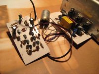
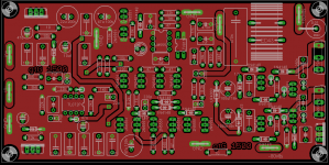
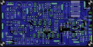
All components come from the junk box (!) Yes, no money for this amplifier, no smd, no ic, no gold plated connectors, no strange japanese transistors.... on two homemade printed boards: a pcb for modulator, a pcb for power stage, 68X35 mm each.
It's perfectly running at 20Vdc (single rail supply, output cap!) on a 2 ohm load, delivering a very very clean, bright and powerful sound.
I've built a second power stage, and I'm planning to modify the modulator to drive two power board in bridged mode (so I can get away this horrible output cap!)
It's based on classd4sure schematics (threads: http://www.diyaudio.com/forums/showthread.php?s=&threadid=40307&highlight= ; http://www.diyaudio.com/forums/showthread.php?threadid=55385 ) (thanks to Chris, Bruno,etc. ), and on the big know-how of the people in this forum (thanks to all)!
Some data:
power Mosfets: IRF540
transistors in modulator: BC557 and BC237
transistors in power stage: all BC337 + 2SD478 (from the deepest and darkest place of my junk box) for stabilized voltage in gate drivers
all diodes: 1N4148, no schottky diodes!
output filter: 28 turns of 0.6mm2 enamel wire, on a ferrite bead... (about 22 microHenry), and 1microF cap
final output cap: a 30 years old, 1000 microF german electrolytic... last attempt to use it in a circuit!
This is the most simple and funny amplifier I have built in 15 years...

I'm proud to present my first UcD amp circuit.
All components come from the junk box (!) Yes, no money for this amplifier, no smd, no ic, no gold plated connectors, no strange japanese transistors.... on two homemade printed boards: a pcb for modulator, a pcb for power stage, 68X35 mm each.
It's perfectly running at 20Vdc (single rail supply, output cap!) on a 2 ohm load, delivering a very very clean, bright and powerful sound.
I've built a second power stage, and I'm planning to modify the modulator to drive two power board in bridged mode (so I can get away this horrible output cap!)
It's based on classd4sure schematics (threads: http://www.diyaudio.com/forums/showthread.php?s=&threadid=40307&highlight= ; http://www.diyaudio.com/forums/showthread.php?threadid=55385 ) (thanks to Chris, Bruno,etc. ), and on the big know-how of the people in this forum (thanks to all)!
Some data:
power Mosfets: IRF540
transistors in modulator: BC557 and BC237
transistors in power stage: all BC337 + 2SD478 (from the deepest and darkest place of my junk box) for stabilized voltage in gate drivers
all diodes: 1N4148, no schottky diodes!
output filter: 28 turns of 0.6mm2 enamel wire, on a ferrite bead... (about 22 microHenry), and 1microF cap
final output cap: a 30 years old, 1000 microF german electrolytic... last attempt to use it in a circuit!
This is the most simple and funny amplifier I have built in 15 years...
Attachments
i too made a ucd using 1n4148 without schottky diodes, it worked but i don't know the disadvantage . not because of ignorance but lack of bat64 or in5819 i used class d from ru scheme BTW exellent schema.
what is the advantage of bc547/bc557 over 2n5551/2n5401 and 1n4148 over schottky diodes
http://www.diyaudio.com/forums/class-d/91773-pictures-circuits-my-diy-class-d-other-projects-9.html ?
what is the advantage of bc547/bc557 over 2n5551/2n5401 and 1n4148 over schottky diodes
http://www.diyaudio.com/forums/class-d/91773-pictures-circuits-my-diy-class-d-other-projects-9.html ?
Hi,
this thread is about 4 years old, so forgive my vague replies.
Well, the basic schematic comes from the patented Philips design UM10155, with some modifications (given by the other discussions at the links in post *1)
http://www.nxp.com/documents/user_manual/UM10155.pdf
I haven't measured that, but the amp is still working "almost" correctly inside a subwoofer enclosure, the sound is clear and the motion of the speaker is good an well controlled.
A lot of simulation was done in 2004 with LTspice by a lot of people of the forum, demonstrating good performance, with an overall low THD. I assume the amp has - in reality- a lot worse THD and frequency response than simulation, but it doesn't matter much to me, considering it's a very low cost amp running a rude subwoofer.
There is no advantage of bc547/bc557 over 2n5551/2n5401, but it's what I had in hand, coming from the junk box... as the 1N4148, a relatively fast diode .... but definitely worse than a Schottky diode!
this thread is about 4 years old, so forgive my vague replies.
Well, the basic schematic comes from the patented Philips design UM10155, with some modifications (given by the other discussions at the links in post *1)
http://www.nxp.com/documents/user_manual/UM10155.pdf
I haven't measured that, but the amp is still working "almost" correctly inside a subwoofer enclosure, the sound is clear and the motion of the speaker is good an well controlled.
A lot of simulation was done in 2004 with LTspice by a lot of people of the forum, demonstrating good performance, with an overall low THD. I assume the amp has - in reality- a lot worse THD and frequency response than simulation, but it doesn't matter much to me, considering it's a very low cost amp
running a rude subwoofer.There is no advantage of bc547/bc557 over 2n5551/2n5401, but it's what I had in hand, coming from the junk box... as the 1N4148, a relatively fast diode .... but definitely worse than a Schottky diode!
Schottky diodes have generally lower forward voltage drop than silicon diodes (about 0.4V vs 0.7V). IN4148 is a small silicon diode quite similar to a typical small Schottky diode. It's fast and with low forward voltage drop (at low current). In that application, it's enough good, but a lot more common and cheaper than a Schottky diode like BAT46 (non SMD).
I had used the schematic from member RX5, taken from thread: http://www.diyaudio.com/forums/class-d/82447-my-1st-ever-d-amp-working.html.
Link at the schematic is no longer available, but I suppose it's not a copyrighted material, so I post it (credit to RX5) :
I had used the schematic from member RX5, taken from thread: http://www.diyaudio.com/forums/class-d/82447-my-1st-ever-d-amp-working.html.
Link at the schematic is no longer available, but I suppose it's not a copyrighted material, so I post it (credit to RX5) :
Attachments
it can operate up to how many vltg +/- ? are the irf540 comfortable or do they heat .
i have done a schematic based on class d from ru the 540 were heating even at +/- 12vlts .i thought it was the rds problem . i changed and used irfb23n20 and still the same problem thats when i thought my signal diodes were the issue . i replaced a 220r resistor with a 440r one on the negative side of the amp and it solved the problem . but i do not have theory proof or calculations to back me up thats why i was so puzzled. recently i used +/- 56vlts it works fine . till a speaker burns and shorts the outputs which destroys them.
i have done a schematic based on class d from ru the 540 were heating even at +/- 12vlts .i thought it was the rds problem . i changed and used irfb23n20 and still the same problem thats when i thought my signal diodes were the issue . i replaced a 220r resistor with a 440r one on the negative side of the amp and it solved the problem . but i do not have theory proof or calculations to back me up thats why i was so puzzled. recently i used +/- 56vlts it works fine . till a speaker burns and shorts the outputs which destroys them.
Attachments
Hi,
If MOS-fets in class-D amps are heating too much, the dead-time between the two control signals is too short. It causes a "shoot-through", a rapid short-circuit of the power supply at every commutation, when both MOS-fets are (fully or partially) switched on together. This results in very short but incredibly intense current pulses through both switching devices, so MOS-fets heat up (and then they fail).
The dead-time depends on the resistor R4 (in the schematic yuo posted), so tweaking the value from 220 ohm to 440 ohm increases the dead-time, so a MOSfet is fully turned off, when the opposite start to turn on.
Have you tried a +/-56V power supply on IRF540? A bit high voltage, IMMO. IRF540 are rated 100V. With 100v parts working, at 112v rail to rail there's a good chance they will fail (and there isn't safety margin).
And protect your speaker! Normal fuses at the output, and on power rails, will save you a lot of money.
thanks alot acid i had been wondering and puzzled GOD bless you big time. i had tried the irf540 at that voltage it works but fails . at that voltage i normaly use irf640 they work fine but if speaker fails the protection does not kick in to save the outputfets. i am not ignorant of using fets with low rds like irfb4227 but they are not there. The only available one is fb23n20 but when i used it with R4 as 220R it heated alot when used R4 as 440R it warmed the 540 and the 640 per
I suggest you to start reading the Application Note AN-1070 (by International Rectifier) http://www.irf.com/technical-info/appnotes/an-1070.pdf
It's a technical paper about the losses (= heat) in MOSfet in class D amps, with a lot of formulas and calculation.
IRFB23N20 is a 200V fet, but has:
- more than 2 times Rds than IRF540
- about 2 times Diode Reverse Recovery Time than IRF540
- more Total Gate Charge than IRF540
- ect.
so it's more hard to switch on and off, and you have a lot more losses than IRF540.
About your question, -/+56V amp can deliver over 300W RMS on 4 ohm load. It's a lot of power for a single speaker. But if you use a +/- 35V power supply, you can use safetly IRF540 obtaining less power, but with less problems in driving MOSfets.
About the short-circuit protection, in the schematic you posted it's based on a 0,01 ohm resistor on positive rail, but the LTV816 has a forward voltage of about 1V, so the protection start at about 100A, if I'm not wrong. Probably too much, IMMO.
Thanks again acid . So if 23n20 cant be used can i use irfp250 or irfp260 like in the ucd 25-1200wts i have the application notes i will try to understand them . I am very poor when it comes to calculations and understanding formulas . But thanks alot i have atleast gotten something .
So if 23n20 cant be used can i use irfp250 or irfp260 like in the ucd 25-1200wts .
Hi stewin, don't get me wrong.

IRFB23N20 is a good MOSfet, and you can use it, and you can use IRFP250 (or others) as well. They have similar data, and you can compare them searching the datasheets on the web.
stewin, you don't do your homeworks!
The answer is on Philips document UM10155 (link at post n.6), pag. 10
Your 440 resistor adjusts dead-time, lower value decreases dead-time and vice-versa.
You have to adjust that value in your circuit, reaching a compromise between:
- too long dead time: high THD
- too short dead time: shoot-through, heat, failure.
If MOSfets are harder to drive, so the drivers need more time to turn-on and turn-off the MOSfets (charge ad discharge the gates), you need a longer dead time to avoid shoot-through.
hi acid i did part of my homework and i saw that Qg is a major determinant when choosing a fet for class d especially when switching at high speed thanks to tripath. looking at various datasheet of various fets i saw that irfp350 and irfp360 were superior to irfp250 also i saw the Qg of irfp260 was too high i think it cannot be used for classd irf640 and irf530 were superior. also noted that the Qg of the fet maters more than Rds
i was wondering how can i adjust the switching frequency in this schematic? thanks to you i found out how to adjust the dead time . reason for adjusting switching frequency is that i can use irfp250 like in the ucd-25-watts-1200-watts-using-2-mosfets
i was wondering how can i adjust the switching frequency in this schematic? thanks to you i found out how to adjust the dead time
. reason for adjusting switching frequency is that i can use irfp250 like in the ucd-25-watts-1200-watts-using-2-mosfets Attachments
- Status
- This old topic is closed. If you want to reopen this topic, contact a moderator using the "Report Post" button.
- Home
- Amplifiers
- Class D
- My DIY UcD amp from the junk box