i was wondering how can i adjust the switching frequency in this schematic?
UCD amps are self-oscillating, and the oscillator frequency is not fixed nor stable.
It depends on:
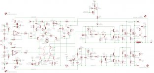
- output LC low-pass filter (L1 and C31 in the schematic you posted): this filter has a cut-off frequency at about 30-35 kHz for a full-range amp, it can be a lower for subwoofer amps.
- feedback RC network (C4, R11, R12) that causes the 180° phase shift needed to keep the oscillator running
and other less important things:
- inductance/load of the connected speaker
- power at the output
- PCB layout
- MOSfets commutation delay
- etc.
For further informations: UcD
As a rule, the feedback RC network keeps the oscillator frequency at about 10 times the cut-off frequency of the output filter, or more, so you can obtain a strong attenuation of the switching frequency on the speaker. A typical UCD amp's oscillator runs from 200kHz to 700kHz, or more.
Slowering frequency too much is generally non a good idea, you have to keep it as high as you can (as high as your UCD amp is running safe and stable), depending on the devices used in the circuit.
Thanks acid it is hard for me to understand the equations and terminologies but i will try to do my homework . just wondering in your schematic why you decided to use one rail vltg and why not use high vltg like +/-80vlts . and can you make a classd amp without the filter cap?
He used single rail because that's what he had lying around. That's why he had to use an output capacitor. Normally you would use a split supply so you can do without that capacitor.
Class D without output LC filter is possible, but NOT UcD which relies on the phase shift of the output filter to keep oscillating. And it is only possible at very low power, <10W, so that the amp doesn't put out significant amounts of radio interference. Speaker lead length must also be kept to a minimum, hence this approach is only used for cellphones, laptops, USB powered speakers and the like.
Class D without output LC filter is possible, but NOT UcD which relies on the phase shift of the output filter to keep oscillating. And it is only possible at very low power, <10W, so that the amp doesn't put out significant amounts of radio interference. Speaker lead length must also be kept to a minimum, hence this approach is only used for cellphones, laptops, USB powered speakers and the like.
Class D without output LC filter
Class D without output LC filter is possible, but NOT UcD which relies on the phase shift of the output filter to keep oscillating. /QUOTE]
Well that's not entirely true, you can create the phase shift separately. The UcD amp I'm building has the two options of feedback from before or after the output LC filter. The design (schematic attached) is based on the Silabs reference design (which only uses pre-filter feedback). Mine is not working yet, admitted, but it will be interesting to compare the two FB methods.
Attachments
Last edited:
I'm still building it, that's what's wrong......elevator, you wrote that your amp is not working, what's wrong?
 Non voglio vendere la pelle dell'orso.
I'm not sure a pre-filter feedback is a good idea. [...] Have you tried the classic post-filter FB?
Well, if you read my post again, I did not say it was a good idea. I just said it is possible, contrary to what Th3 uN1Qu3 affirms. Also, I said that in my amp I am implementing both pre- and post (selectable), for A-B comparisons and tweakings
Cheers,
E
The UcD patent and original appnote are describing a self-oscillating amplifier with post filter feedback.
Ok got it. Now would that mean that pre-filter FB does not infringe on the Hypex IP? Sweet...
stewin,
thanks for sharing this, and for keeping us update on your progress.

Bad news: that website requires registration for viewing the attached files.

it is simple just enter name and email address same as here at diy. but will also upload pictures.
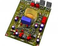
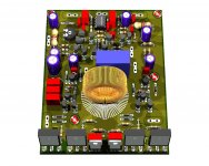
by any chance do you know of a good available non smd transistor for totem pole and gate drive which can handle parallel mosfets comfortably . below is schema and photo of project.
by any chance do you know of a good available non smd transistor for totem pole and gate drive which can handle parallel mosfets comfortably . below is schema and photo of project.
Attachments
by any chance do you know of a good available non smd transistor for totem pole and gate drive which can handle parallel mosfets comfortably . below is schema and photo of project.
Some japanese transistor are rated 160V 1A, in case TO92.... not very common indeed! Zetex also makes someting similar in case "E-line". Others are in TO220 package, with larger current capability.
hi all where does one adjust the switching freq in this schema?
Please see previous post n.21.
In the schematic attached, the switching frequency is mainly set by low pass filter (L1+C15), and feedback network (C17+R31+R32).
Attachments
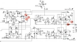
thanks acid . i want to slow this amp down to 250khz so as to use irfp250 . so if i use 100uh inductor and c15 to 0.47uf will it do the trick?
From the values given for the output LC filter, it has a cut frequency at about 23KhZ (-3dB), too low for a good full-range amp. Anyway, I think that switching frequency is not proportional to LC filter cut frequency, and a slow MOSfet has a long commutation delay
 . Probably you need also to tweak the feedback network, and check what happens. I have never tried it.
hi all it has been quiet here. ive got good news . katrinos amp works well and he has plenty of videos posted at youtube . i made a similar type of this amp but with a chip
the link is below
have fun all
ucd 25 watts to 1200 watts using 2 mosfets
the link is below
have fun all
ucd 25 watts to 1200 watts using 2 mosfets
- Status
- This old topic is closed. If you want to reopen this topic, contact a moderator using the "Report Post" button.
- Home
- Amplifiers
- Class D
- My DIY UcD amp from the junk box