Hi !!
I bought from Digikey, 6 TDA8920BJ IC's.
It needs a 22uH + 680nF output filter to work with 4Ohms load, and 47uH + 330nF to work with 8 Ohms. Question... Why does it need different output filters to work with different loads? It isn't just a low pass filter to take PWM signal away from the speaker
Well ! I REALLY want to hear this little thing, It's my first D amp, and I'm quite excited ! I can't get inductor easily around here, so I want to build my own. I have here on the shelf a enlammed copper wire 18AWG, and a bunch of old computer PSUs. Can I make my inductor from this? What about an aircore inductor, does it sounds better ? I also can buy ferrite core, and wind in myself, and of course, to buy it I must know the size that I don't have any idea yet !
Thank you so much !!!!!
Best Regards !
Very VERY large you mean ! For 47uH it would need > 2000 turns
I need calculate it for ferrite core !
This would work fine for me:
http://uk.farnell.com/jsp/Passive+C...OGIES/1422311C/displayProduct.jsp?sku=1077056
BUT... I live in brazil, the land of corruption, and this sh**T costs 26 reais, 13usd... Ridiculous for a simple inductor, and I need two for each amp. !
I found a Store that have everything to make inductors, many types of ferrite, and all sizes of copper wire.
I need some technical information before go there and buy these components. Which ferrite former is better?
The amp works with +/- 27v, and is 2 Ohms compatible. What is the recommended current rating for the inductor ?
Thank you very much !
I need some technical information before go there and buy these components. Which ferrite former is better?
The amp works with +/- 27v, and is 2 Ohms compatible. What is the recommended current rating for the inductor ?
Thank you very much !

Sorry I can't answer your questions, but here is a very handy calculator for ferrite and iron powder cores.......
http://www.66pacific.com/calculators/toroid_calc.aspx
http://www.66pacific.com/calculators/toroid_calc.aspx
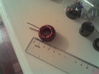
I couldn't wait for an answer, and I went to the store and bought some ferrite cores. They were VERY cheap. I just finishied winding it right now, and here is the picture of the inductor.
The wire is 18AWG, 28 turns, how much uH do you guys think that it have?
Thank you !
The wire is 18AWG, 28 turns, how much uH do you guys think that it have?
Thank you !
Attachments
-_nando-_ said:I couldn't wait for an answer, and I went to the store and bought some ferrite cores. They were VERY cheap. I just finishied winding it right now, and here is the picture of the inductor.
The wire is 18AWG, 28 turns, how much uH do you guys think that it have?
Thank you !
You must know material type and size to calculate the inductance.
If these are ferrite toroids (0.9 inches?) you get 1000uH (1mH) with material 68, that has low permeability (20) and about 35mH (35000uH) if material type is 43 (850 perm).....
I don't think this is the right material for the application.
Take T106 Iron Powder cores with low perm. The red type (perm 10) needs 59 turns of wire to get 47uH. If you use 20AWG the turns will fit in a single layer.
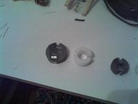
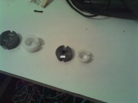
I also have two ferrite cores, one is type 62 and other is 49. The Type 62 is bigger, and have a hole diameter of 15mm and 5mm of lenght.
The type 49 have a hole diameter of 13mm and 10mm of lenght.
I'm not sure about the ferrite types, so I took a picture of it, as it was difficult to read I wrote using mspaint what is marked on it.
Take a look:
The type 49 have a hole diameter of 13mm and 10mm of lenght.
I'm not sure about the ferrite types, so I took a picture of it, as it was difficult to read I wrote using mspaint what is marked on it.
Take a look:
Attachments
I used the following Digikey parts for the TDA8920:
M1425-ND (22mH for 8ohm bridged)
M1422-ND (12mH for 4ohm bridged)
I initially used a smaller coil with an 8-10A rating but it got quite hot and I had to replace it (hysteresis losses). These coils run cool.
M1425-ND (22mH for 8ohm bridged)
M1422-ND (12mH for 4ohm bridged)
I initially used a smaller coil with an 8-10A rating but it got quite hot and I had to replace it (hysteresis losses). These coils run cool.
An externally hosted image should be here but it was not working when we last tested it.
nando,
I doubt if anyone is going to spell out how to design an inductor for you. The following website has lots of good information. You need to know how much DC current you have to support and will need to use either a gapped core or a powder core. http://www.smps.us/magnetics.html
Rick
I doubt if anyone is going to spell out how to design an inductor for you. The following website has lots of good information. You need to know how much DC current you have to support and will need to use either a gapped core or a powder core. http://www.smps.us/magnetics.html
Rick
Neil Davis: Thank you very much ! How does your amp sound? Now, I know that the inductor should be > 12.6A of current rating. Buy digikey parts here is damn expensive, the TDA8920 costs just 10x more buying in a quantity of 6 pieces ! I really must wind my own inductor. I think that it's not that difficult.
thomaselliot: Could you explain me the maths to calculate the inductors? Are these ferrite cores really type 62 and 49 or is it just a number "floating" at the ferrite's surface?
sawreyrw: I REALLY don't know what are the specs needed for the inductors, since the TDA8920 doesn't provide any information about the inductors.
What I know is that I must have a 22uH inductor, and using Neil Davis experience, it should be at least 12.6A.
Best Regards !
-_nando-_ said:Neil Davis: Thank you very much ! How does your amp sound?
The amps works, but to be honest with you, I've never really tried it with good speakers. This amp was supposed to provide the bass channel for an active 3-way system which used the AD1994 for the mid and tweeter amps. I had trouble getting the AD1994 circuit board correct and there was some software to control a TAS3004 on the AD1994 board that still isn't complete. So I put the TDA8920 board on the shelf until about a month ago. I've got it in a chassis now but still haven't gotten around to final wiring so I can really listen to it. Just too many projects underway right now and not enough time.
Let me blunt about about building this amp: I think that the output filter may end up being the least of your problems. The output is constantly switching between the rail voltages at 320KHz and when the amp is running there can be very high current flowing. If you don't have a good circuit board layout this amp will not behave well. All of those SMD capacitors are essential and the circuit paths have to be short! So I think you will find that the circuit board layout is going to be the real challenge in getting these chips to work.
I didn't want to go through a long learning process with this amp so I copied the layout of a proven design--the one in the data sheet. I used the ExpressPCB to lay it out, and I will post these files if you want them. You are going to have to buy those SMD parts from Digikey anyway, so why not add the inductors to the list? They are only $5 and the circuit boards are going to cost you a lot more than that.
BTW, I never did figure out what the best materials were for the inductor core. There is a lot of information and general guidelines such as using powdered iron, Kool-Mu and gapped cores, and I did a lot of reading, but finally ended up using an experimental approach. Not a real easy subject to master, even for an EE.
I like your crude inductor. Maybe this fancier version would work better--
An externally hosted image should be here but it was not working when we last tested it.
Hi Neil !
The boards costs near nothing to me, as I can make it at home with professional quality !
All digikey parts are seriously taxed by the government here, and a 5 bucks thing can become very expensive. Anyway, I've already bought the chip, and if I buy any other thing from digikey, I must pay a painful shipment tax of 94usd Hehehe still not impressed?
About the layout, don't worry, I'll do my best and believe, I'm good with layout design, although I hate to do it !
Made in home circuit, layout and board ! Take a look...
The boards costs near nothing to me, as I can make it at home with professional quality !
All digikey parts are seriously taxed by the government here, and a 5 bucks thing can become very expensive. Anyway, I've already bought the chip, and if I buy any other thing from digikey, I must pay a painful shipment tax of 94usd
Hehehe still not impressed? About the layout, don't worry, I'll do my best and believe, I'm good with layout design, although I hate to do it !
Made in home circuit, layout and board ! Take a look...
Attachments
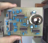
-_nando-_ said:Made in home circuit, layout and board ! Take a look...
Good luck, but take a careful look at the SMD chips that are on the back of the board in the photo of my amp (see inset in the upper right corner). That's the decoupling that is required for the TDA8920. There are some fairly small feed-throughs (vias) that you are going to need. Not impossible with home techniques, but there are some good challenges here.
I vaguely remember someone describing some trouble they had with decoupling with this amp. Do a search on this forum for 8920--you might find something that will help.
On the inductor issue, you might want to register for this event:
http://www.techonline.com/learning/webinar/202101427 . It's a free webcast on Oct 10 from TI on designing LC filters for digital amps.
nando, perhaps you should register for this online seminar about PWM filter design.......
http://www.techonline.com/learning/webinar/202101427
I plan on viewing it even though I'm sure a lot of the discussion will be above my understanding of these things.
EDIT: OK, I was very tired when I posted this and did not read the above post. Very strange coincidence.
http://www.techonline.com/learning/webinar/202101427
I plan on viewing it even though I'm sure a lot of the discussion will be above my understanding of these things.
EDIT: OK, I was very tired when I posted this and did not read the above post. Very strange coincidence.
Neil Davis said:I like your crude inductor. Maybe this fancier version would work better--
Oh No! Now you've done it, Neal. Everybody is going to want one of those crystal inductors now......
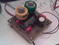
I've sucessfully built the amp !
It sounds GOOD, very pleasant sound, very accurate highs and good bass. The cone control seems to be also very good.
The inductors are Air Core, I've built them based on:
http://www.pronine.ca/multind.htm
I enjoy it very much, I have a very small dissipator, and it works fine with.
The inductors runs less than warm, is this fine?
No HUM or Hiss at all.
Attachments

- Status
- This old topic is closed. If you want to reopen this topic, contact a moderator using the "Report Post" button.
- Home
- Amplifiers
- Class D
- I've got a D-AMP, how to build my inductor ?