I’m designing a 1200V half-bridge PWM amplifier as a plate modulator for a vacuum tube class C AM RF transmitter. Upper audio bandwidth limit is 3kHz and the switching frequency is 100kHz.
Switching frequency ripple voltage at the output needs to be rather low (than for speaker driving applications), so a multiple pole LPF will be required at the output. However, the ability to apply a fair amount of global NFB would be desirable.
Any suggestions?
Cheers,
Glen
Switching frequency ripple voltage at the output needs to be rather low (than for speaker driving applications), so a multiple pole LPF will be required at the output. However, the ability to apply a fair amount of global NFB would be desirable.
Any suggestions?
Cheers,
Glen
No takers? 
FWIIW I’ll restate my dilemma. I need to attenuate all harmonics of the 100kHz switching waveform by at least 60dB, but I can't see an easy way to apply any substantial amount of NFB from the output due to the phase shift incurred by the filter.
Maybe there isn’t a workable solution, meaning I’ll just have to run the thing open loop??
Cheers,
Glen
I've heard others who use multiple pole filters mention that they take feedback from before and/or after the first LC filter section and leave the rest of the filter outside the feedback loop.
Your design requirements mean you'll need some pretty large inductors, in value and physical size; especially if you want to keep losses low.
Your design requirements mean you'll need some pretty large inductors, in value and physical size; especially if you want to keep losses low.
Actually something along these lines is what I was thinking of, but picking off the NFB part way through the filter can lead to some pretty interesting pass-band effects.
I figured that there might be some kind of established design procedure to this kind of problem, but Google unfortunately turns up very little on class D filter design (at least with my searching abilities).
Cheers,
Glen
I figured that there might be some kind of established design procedure to this kind of problem, but Google unfortunately turns up very little on class D filter design (at least with my searching abilities).
Cheers,
Glen
There is always some form of current mode control. While more complex, it does simplify things. It turns the inductor in the filter into a constant current source, which leaves a first order filter on the output. The added inner current loop can lead to issues with 1-cycle vs 2-cycle ("fast" bifurcation) stability.
IIRC there was a "leapfrog" filter of sorts that used voltage and current feeback from the shunt capacitors and series inductors of an output filter.
IIRC there was a "leapfrog" filter of sorts that used voltage and current feeback from the shunt capacitors and series inductors of an output filter.
Found it. Thanks!
http://www.diyaudio.com/forums/showthread.php?s=&threadid=40388&highlight=
Cheers,
Glen
http://www.diyaudio.com/forums/showthread.php?s=&threadid=40388&highlight=
Cheers,
Glen
Hmm.....that Leap Frog method is clever, but implementing a real life version at with the number of filter elements and operating voltages I need would be a bit of an exercise  . I also really need a fixed frequency design.
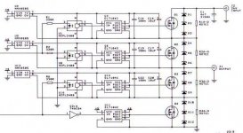
Anyway, if anyone is interested, attached below is my 2kV+ half bridge circuit. MOSFETs are low capacitance high voltage units from Sanyo. D1-D6 are beefy transorbs to clamp Vds. Works very well to over 3kV, but the topmost DC-DC converters begin to break down eventually
Cheers,
Glen
. I also really need a fixed frequency design.Anyway, if anyone is interested, attached below is my 2kV+ half bridge circuit. MOSFETs are low capacitance high voltage units from Sanyo. D1-D6 are beefy transorbs to clamp Vds. Works very well to over 3kV, but the topmost DC-DC converters begin to break down eventually
Cheers,
Glen
Attachments
Okaayyy.........
After considering my options I’ve decided to run the LPF open loop. NFB is still mandatory though, so I guess I’ll be feeding the PWM waveform directly from the MOSFET half bridge back to the input summer.
I figure that if I just make my opamp based input error amplifier an inverting integrator my dominant pole will be set here.
Lets say I apply 20dB NFB. I require only 3kHz audio bandwidth for (legal) voice communications, so the dominant pole can be set as low as 3kHz/20dB = 300Hz.
Since my fixed PWM clock frequency is 333.33 times higher than this at 100kHz, I figure that the fed-back PWM waveform will be adequately conditioned for me by the intergrating summer. Yes? No?
Honest question for the class D experts out there - Does it sound like I know what I’m talking about? Workable / feasible?
Cheers,
Glen
You can use tuned LRC series notches in parallel with the output to tame the fundamental and the first two harmonics... Higher harmonics are not likely to be a problem...
Otherwise, an output filter like 1mH and 3.3uF will provide full output swing up to 4Khz (no load) and -60dB attenuation at 100Khz... Such a filter will resonate around 2.8Khz but you can tame it with enough negative feedback or a self oscillating UcD-like control scheme...
Otherwise, an output filter like 1mH and 3.3uF will provide full output swing up to 4Khz (no load) and -60dB attenuation at 100Khz... Such a filter will resonate around 2.8Khz but you can tame it with enough negative feedback or a self oscillating UcD-like control scheme...
I’ve been experimenting in sim with a slightly fudged Butterworth LCLC lowpass filter with a corner frequency of about 3.5kHz and designed around the characteristic impedance of the load. Probably unconventional, but I’m getting a rather adequately flat pass band, even so I’m not driving the filter with a matched impedance.
A single LC would attenuate the 100kHz fundamental by 60dB providing that the Q factor of the components was very high.
I’d also like to retain a fixed frequency topology, so that I can beat out any potential birdies in my receiving equipment, if necessary
Cheers,
Glen
A single LC would attenuate the 100kHz fundamental by 60dB providing that the Q factor of the components was very high.
I’d also like to retain a fixed frequency topology, so that I can beat out any potential birdies in my receiving equipment, if necessary
Cheers,
Glen
- Status
- This old topic is closed. If you want to reopen this topic, contact a moderator using the "Report Post" button.
- Home
- Amplifiers
- Class D
- Global NFB with muitiple pole output filter