Hi to all,
Since my last project streo class-d amp with HIP4081 I am trying to implement a good input section to improve sound quality. Althoug my amp is good on sound scope results tell me some improvments.
Any way I tried a discrete input comparator section of UCD amp. This comparator eliminates input opamp/integrator. Probably it is very usefull for full bridge desing but, for an half bridge one have to implement a FB network to it.
You all experienced DIY'ers on Class-D "Baldin,,Fumac, RX5, Luka, BWRX and others" please tell me how can I implemet the FB network to this input?
All comments are will be helpfull.
File enclosed on SWcadIII
Best Regards
Attachments
Try modeling the HIP4081 as a transmission line with propagation delay (~50ns typical or ~100ns max according to the HIP4081 datasheet) and the mosfets as current or voltage controlled switches. Add the LC output filter and feedback loop and you can start experimenting with component values. Look at the diagram in the first post of the "Philips UCD application note" to see the feedback network and some component values that will help get you started.
Thanks BWRX,
I enclosed a signal result. This input section is not only for HIP4081 but also IR2113( R1 still adjusting the dead time). Power supply lines can go up to +/-50 or +/-60V for a high power full range amp. I do not thinking about a IC version of UCD. As you can see it has a triangle wave input. Therefore it is not self osc. type. Inverting input of this comp will get overal audio signal and FB. Question is that, should I use the FB network after the filter inductor?
Regards
Attachments
Ok , Ok I see and the answer resulted itself by reading Bruno Putzeys' AES paper. I understand that , Hysterisis mode swiching can be achieved before the filter inductor and UCD mode is more audible than hysterisis mode. OK, see the enclosed IC version of UCD . It is based on a slow mosfet driver LT1160.
I will try this input modulator with IR2113. The resistor (R1) adjusts the dead time but this time decreasing its value inreases the dead time.
Ok, What can be the advantage of this circuit and what do you think is it valuable to create so kind of an amp?
Regards
I will try this input modulator with IR2113. The resistor (R1) adjusts the dead time but this time decreasing its value inreases the dead time.
Ok, What can be the advantage of this circuit and what do you think is it valuable to create so kind of an amp?
Regards
Attachments
Hi, As I see, i am discussing something myself  . I introduce the discrete modulator to IR2113 and HIP 4081. While IR2113 is modulating at 280Khz , HIP modulates at 109Khz with 100K Del. resistors(probably decrasing del resistors would give higher oscillating f). But, the strange thing not heat on mosfets with both IC drived UCD. I played with dead time resistor R1 and increased it to 1K. On lower values of R1 (330,390,470,510,680) there is a bit more distorted sound because of higly increased dead time. This is the IC promoted UCD . I think this is a good experimentig circuit and DIY'ers can love it.
If someone will not give reply, moderators should delete this thread.
Regards
. I introduce the discrete modulator to IR2113 and HIP 4081. While IR2113 is modulating at 280Khz , HIP modulates at 109Khz with 100K Del. resistors(probably decrasing del resistors would give higher oscillating f). But, the strange thing not heat on mosfets with both IC drived UCD. I played with dead time resistor R1 and increased it to 1K. On lower values of R1 (330,390,470,510,680) there is a bit more distorted sound because of higly increased dead time. This is the IC promoted UCD . I think this is a good experimentig circuit and DIY'ers can love it. If someone will not give reply, moderators should delete this thread.
Regards
Hi Whortless. Please don't get discouraged if you don't get many replies. You're working on something that not a lot of people understand very well - I'll freely admit I fall into that group!
I don't have my windows computer anymore, so I can't open the asc file. Any chance you could post a GIF image of the SwCAD schematic?
Experimenting is one of the best ways to learn how part changes affect circuit operation. You've read some good documents all ready. There's also a good thread by SSassen about designing/building a non-discrete UcD amp. Might be worth having a read through it: http://www.diyaudio.com/forums/showthread.php?threadid=58476
Hi, BWRX
Thanks for the reply. I enclosed the lastes shematic version in GIF format. In my view the advantage of using a mosfet driver is not to striving with component values of two PNP transistors in UCD.
Now, let us to try the increasing the sw frequency for better sound quality.
Regards
Thanks for the reply. I enclosed the lastes shematic version in GIF format. In my view the advantage of using a mosfet driver is not to striving with component values of two PNP transistors in UCD.
Now, let us to try the increasing the sw frequency for better sound quality.
Regards
Attachments
Hi All,
Try this on last shematic ; R1=680, R11=33K, C8= 470p and R12,R6,R5+ C10,C5,C2=open. Get the FB before the filter inductor. What the swiching topology is now?
Driver IR2113 and I get 500Khz without heat. Tomorrow I will show the scop results if I could get. Hýým , Do not forget to apply audio signal otherwise will not oscillate.
Regards
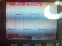
Here one of the scop picture
Hi,
Here one of the scop picture. It is running with IR2113+IRF540N 22R gate and 680R dead time resistors. Last version used (hyteresis mode?) integretor cap 1nf, FB 33K.
I know it is not quite to show all the results. But sound is better than my HIP4081 delta-sigma modulated amplifier in my room. Also the amp is runnig on bread board, therefore a good desined PCB can give a better result( I measured 20.42V RMS on 4ohm speaker with +/-35V split supply before the distorsion). SW frequency is adjustible by changing the integrator cap's (C8) value, 500Khz is an obtainable one but 260Khz is moderate and audible.
Waiting for the comments
Regards
Attachments
Hi,
Hey luka where were you! I started to miss you, because u are a very helpful DIYer.
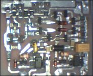
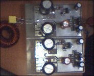
Any way, to day I did my small UCD. It works at 370Khz on idle. All the components are SMT except the IRFP250Ns. Here is the tested channel's photo. Other will be tested soon. It is an easy and cheap amp. Some times it is very hard to find some special components, therefore I could not decide to put which one to my car. HIP4081 amp will wait for other four channel for my home theatre and UCD will go in to my sub's box. I am planning to add four fullrange channels to this one and certainly will add some protection circuits.
If a diyer interested I can post the PCB files and shematic of this amp. I tested this with single ended input but, one can put differantial inputs to it.
Regards
PS. sorry for the low resolution, my KODAK's charger broken and waits for me to repair it.
Hey luka where were you! I started to miss you, because u are a very helpful DIYer.
Any way, to day I did my small UCD
. It works at 370Khz on idle. All the components are SMT except the IRFP250Ns. Here is the tested channel's photo. Other will be tested soon. It is an easy and cheap amp. Some times it is very hard to find some special components, therefore I could not decide to put which one to my car. HIP4081 amp will wait for other four channel for my home theatre and UCD will go in to my sub's box. I am planning to add four fullrange channels to this one and certainly will add some protection circuits. If a diyer interested I can post the PCB files and shematic of this amp. I tested this with single ended input but, one can put differantial inputs to it.
Regards
PS. sorry for the low resolution, my KODAK's charger broken and waits for me to repair it
.Attachments
Hi
I have some problems with my ISP, I am going to FTTH from VDSL so I am currently still without internet, but I have found one wireless network that has connection to internet so for the moment I have free net.
Now back to subject, glad to hear that I am helpfull to someone, THANKS
Amp looks very good, nice and small. I like it
I have some problems with my ISP, I am going to FTTH from VDSL so I am currently still without internet, but I have found one wireless network that has connection to internet so for the moment I have free net
.Now back to subject, glad to hear that I am helpfull to someone, THANKS
Amp looks very good, nice and small. I like it
Hi, Luka
Please excuse me, could not write. I understand the situation and get sadden.
I gaveup the discrete input modulator for mosfet driver ICs project. Although, sound qualities better to my ears, simulation results show some distorsions because of longer dead times. Also here I need to define the topology (it is out of my knowledge). In principle it works like a sigma-delta modulator but, infact I do not know.
UCD is an easy and cheap amplifier and not requiers special components. I recently did through hole version of UCD. It was good. But, the simplicity of the amplifier force me to search more complex class-D amps. I realised now the simple UCD is the solution of my car Class-D amplifier project.
Any way the circuit works very good and a pretty amp.
Regards
Please excuse me, could not write. I understand the situation and get sadden.
I gaveup the discrete input modulator for mosfet driver ICs project. Although, sound qualities better to my ears, simulation results show some distorsions because of longer dead times. Also here I need to define the topology (it is out of my knowledge). In principle it works like a sigma-delta modulator but, infact I do not know
.UCD is an easy and cheap amplifier and not requiers special components. I recently did through hole version of UCD. It was good. But, the simplicity of the amplifier force me to search more complex class-D amps. I realised now the simple UCD is the solution of my car Class-D amplifier project.
Any way the circuit works very good and a pretty amp.
Regards
- Status
- This old topic is closed. If you want to reopen this topic, contact a moderator using the "Report Post" button.
- Home
- Amplifiers
- Class D
- Discrete input modulator