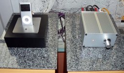
I have seen so much dedicated to the "modding the Trends" thread (having posted on it and now receive prompts) that I cannot understand why more of you have not modded the Kensington S2000 i-pod dock.
Check out the "is this the cheapest T-Amp in U.K" or something similar and get along to you nearest Richer Sounds. I have 4 modded S.I's a Trends 10.1 and a Teac Tripath amp. My amp of choice is the modded Kensington (and yes I left the tiny inductors as standard !)
Check out the "is this the cheapest T-Amp in U.K" or something similar and get along to you nearest Richer Sounds. I have 4 modded S.I's a Trends 10.1 and a Teac Tripath amp. My amp of choice is the modded Kensington (and yes I left the tiny inductors as standard !)
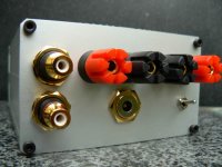
audio1st said:I even managed to use the i pod docking part..
Tidy job there Barry

http://i73.photobucket.com/albums/i239/saxonsex/2006_0718Review0007.jpg
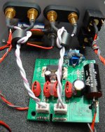
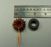
These are the toroids I used. I will try removing some of the wire. I have used some in a modded Sonic Impact and it sounds brilliant.
These are the toroids I used. I will try removing some of the wire. I have used some in a modded Sonic Impact and it sounds brilliant.
Audio1st. Many thanks for your reply. It has occurred to me that as the input goes in at the same place, is it simply a matter of reducing the overall size of the pcb, or does chopping it in half result in better sound quality ?
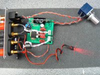
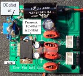
I assume that the picture you produced for me shows the Auricaps for illustration purposes only, and that the SCR caps on the previous picture are one on top and one underneath the board ?
It also appears that there may be a connection where C37 & C38 (next to the end of the SCR cap) were removed ?
Sorry so many questions, but finally.. i assume that the C54 & C55 100uf are not needed as these have been removed.
Audio1st. Many thanks for your reply. It has occurred to me that as the input goes in at the same place, is it simply a matter of reducing the overall size of the pcb, or does chopping it in half result in better sound quality ?
Just so it fits in the case..
I assume that the picture you produced for me shows the Auricaps for illustration purposes only, and that the SCR caps on the previous picture are one on top and one underneath the board ?
Correct..
It also appears that there may be a connection where C37 & C38 (next to the end of the SCR cap) were removed ?
No connection between C37 & C38, just between the SCR cap and the board..
Sorry so many questions, but finally.. i assume that the C54 & C55 100uf are not needed as these have been removed.
Correct again..
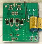
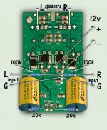
The attatched picture shows an impression of a better board layout if you cut it even smaller..(as Lee did)..
Attachments
- Status
- This old topic is closed. If you want to reopen this topic, contact a moderator using the "Report Post" button.
- Home
- Amplifiers
- Class D
- U.K Modders missing a trick ?!