Placement of external ports
I am constructing half a boominator (and then some), and have most things worked out except for the ports.
Question 1: Should the volume of external ports be included in the calculation of the box volume?
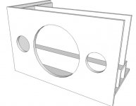
Question 2: How does it affect sound if I place the external port against the center brace, like this:
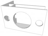
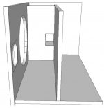
The key points of the above design are
Question 3: How far apart can SLA batteries be placed when connected in parallel?
PS: Thanks for all the enlightenment you all have provided in this thread! Although it took some time to get through 2800 posts...
I am constructing half a boominator (and then some), and have most things worked out except for the ports.
Question 1: Should the volume of external ports be included in the calculation of the box volume?
Question 2: How does it affect sound if I place the external port against the center brace, like this:


The key points of the above design are
- Back-to-back mount of two drivers (HP10W).
- Match the frequency curve of the Boominator.
- Each side is a mirror image of the other side so that each channel (1 driver + 1 port + 2 piezos (KSN1001A)) can be concentrated around each end of the box, while still having a sense of stereo from the front and back. I hope that this placement will diminish some of the problems with having only two drivers.
- Two batteries (2 x 3.2Ah) will be fixated under each port.
- One solar cell (PT15-300) will be placed on the top of the box, at the center.

Question 3: How far apart can SLA batteries be placed when connected in parallel?
PS: Thanks for all the enlightenment you all have provided in this thread! Although it took some time to get through 2800 posts...
Halfinator with bottom compartment
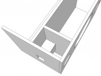
As an alternative to the half-bominator in #2801, I have another design with one internal port per channel and the compartment at the bottom:
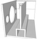
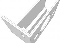
The key points of the above design are
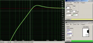
To get the box in a shape close to the golden ratio (501 x 310 x 310), I had to calculate with a volume of 13.4 L:
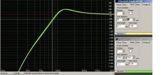
Question 2: The velocity of the port is very high, but from #2799 I gather that this is actually a good thing because it helps to limit too low frequencies, right?
As an alternative to the half-bominator in #2801, I have another design with one internal port per channel and the compartment at the bottom:


The key points of the above design are
- The batteries can be placed at the bottom, right in the middle of the box to give good ballance.
- All electronics can be placed on a sled (if serviced from the ends) or on a lid (if serviced from the bottom).
- The top of the end pieces are inforced for carrying (and helps obtain thickness of the ports).
- The drivers' magnets can be glued on the bottom compartment (as well as the center brace), making the box even more stiff (and probably making assembly easier as well).
- Each side is a mirror image of the other side so each channel will only have one port.
- The two piezos in each end will play the same channel as the port at that end.
To get the box in a shape close to the golden ratio (501 x 310 x 310), I had to calculate with a volume of 13.4 L:

Question 2: The velocity of the port is very high, but from #2799 I gather that this is actually a good thing because it helps to limit too low frequencies, right?
Last edited:
If someone really does want to use wool anyway, sheep wool would be the best option as it dries easily.No stuffing needed or wanted. Stuffing of any kind unfortunately absorbs and retains moisture.
But listen to the master, as always...
Have anyone thought of installing some kind of "wake up" thing for the amp? The reason I ask is that some one borrowing our Boominator destroyed 4 SLA's by leaving the Boominator on after the party was over (for many weeks). This was a rather expensive mistake, and we want to avoid this by either installing a power-led, or maybe somehow get the amp to automatically switch on and off, depending on if there's input signal or not.
My concerns are that a power-led seems to use 1/4W, which I think is a lot (but maybe necessary) and that a "wake up" might be either expensive or complicated.
Anyone have thoughts on this matter?
My concerns are that a power-led seems to use 1/4W, which I think is a lot (but maybe necessary) and that a "wake up" might be either expensive or complicated.
Anyone have thoughts on this matter?
Solar--charge in the almost dark.
This can make sure the output voltage of your solar panel is always right to charge a battery. A 15v in bright sun solar panel can't charge a 13.5v battery in the shade without a buck boost converter at the output of the solar panel. You'd also want an MBR735, MBR1035 or other high efficiency diode at the output of the buck boost converter. The item linked is more efficient since it doesn't have a CCS; however, that fact limits it to 10 watt or smaller solar panels (whereby the size of the solar panel performs the current limiting to ~10w although the device may could withstand ~15w). Although the ideal voltage is 13.5 (for my battery--check your specs, they vary), you may need to set it to 13.8v in order to swamp the voltage drop of the series diode (see current versus forward voltage drop chart in the datasheet of your specific Schottky diode).
Conveniently, the inexpensive adapter allows using any solar panel with operating voltages in the range of 2 to 15 volts. Solar panels normally sag at least 5 volts under load (they vary--check specs), so a minimum solar panel produces at least 7v.

You'll need a (pushbutton) defeatable lockout to allow charging to occur, so that if the unit is forgotten, the solar panel will have eventually charged it up.
This can make sure the output voltage of your solar panel is always right to charge a battery. A 15v in bright sun solar panel can't charge a 13.5v battery in the shade without a buck boost converter at the output of the solar panel. You'd also want an MBR735, MBR1035 or other high efficiency diode at the output of the buck boost converter. The item linked is more efficient since it doesn't have a CCS; however, that fact limits it to 10 watt or smaller solar panels (whereby the size of the solar panel performs the current limiting to ~10w although the device may could withstand ~15w). Although the ideal voltage is 13.5 (for my battery--check your specs, they vary), you may need to set it to 13.8v in order to swamp the voltage drop of the series diode (see current versus forward voltage drop chart in the datasheet of your specific Schottky diode).
Conveniently, the inexpensive adapter allows using any solar panel with operating voltages in the range of 2 to 15 volts. Solar panels normally sag at least 5 volts under load (they vary--check specs), so a minimum solar panel produces at least 7v.
Thick polyester/nylon/kevlar acoustic pad (or mesh) with the consistency of ScotchBrite scouring pads, don't retain water at all. No sheep were harmed.No stuffing needed or wanted. Stuffing of any kind unfortunately absorbs and retains moisture.
Theoretically off would be good at 9v; however, transients will pull down the figure a bit since a battery charged only to 9v has weaker current delivery, so you'd have a "somewhat less than 9v figure to work with.You can probably buy a battery disconnect switch, that kills power to the system if the battery voltage drops below a certain point. If such a thing doesn't exist, it would be ridiculously easy to design/build.
You'll need a (pushbutton) defeatable lockout to allow charging to occur, so that if the unit is forgotten, the solar panel will have eventually charged it up.
Last edited:
No stuffing needed or wanted. Stuffing of any kind unfortunately absorbs and retains moisture.
Ah okey, thats what I thought cause it hasn't been mantioned before.
Before I put everything together I just had to play it to see or hear how it sounds.
Damn it plays loud!
I havent gone to max volume yet cause I do not dare to, didnt think it could play so loud
So amazing when u feel the kick pumping in your chest
Now I need to wait for next weekend before I can finish it... Damn work!
I will upload som pictures when i'm done.
Thick polyester/nylon/kevlar acoustic pad (or mesh) with the consistency of ScotchBrite scouring pads, don't retain water at all. No sheep were harmed.
Technically that's even worse as non-organic stuffing works as humidity condensers making you risk having standing water inside your speaker after consecutive days of use.
You have to remember the use conditions here. It's intended for use directly on the grass, during summer where daytime temperatures is easily 30 degrees and night time easily under 10 degrees. As humidity is always high near the ground/grass you get some very difficult circumstances the speaker has to work under.
What are your thoughts on rough finish wood (for the inside) instead of slick finish wood?Technically that's even worse as non-organic stuffing works as humidity condensers making you risk having standing water inside your speaker after consecutive days of use.
You have to remember the use conditions here. It's intended for use directly on the grass, during summer where daytime temperatures is easily 30 degrees and night time easily under 10 degrees. As humidity is always high near the ground/grass you get some very difficult circumstances the speaker has to work under.
What are your thoughts on rough finish wood (for the inside) instead of slick finish wood?
I certainly recommend sealing all exposed wood, both inside and outside. Remember one prototype I had with me a very rainy and damp festival where I hadn't even painted the plywood. The speaker was almost 1 kg heavier when I got home than what it was going there.
Hello Saturnus
I am trying to build one of these for Roskilde this year. I have acquired the 12V batteries and the solar panels. Now I am looking for the amplifier and the speakers. My problem is that the 41hz amplifiers seems to be out of order and they don't know when it will get restocked. Can you recommend another amplifier to me?
(I am not experienced in soldering components onto a print board, so preferably I would like the amplifier to work out of the box)
Great guide by the way and I picked your design solely on the sustainable way it works with solar powered batteries. It is a very nice idea.
Thank you in advance
Kri5t
Sorry if this has already been brought up, but does anyone know what type of DC male plug you insert into the preassembled AMP6B? I've tried with a few different types lying around my house, but I haven't been able to find one that fits yet.
And if you know what size of DC plug is needed, is there any chance someone also knows where I can buy that kind of plug? Preferably with a cable already mounted, or some really cheap adapter I can just remove after buying it.
Thanks a lot!
And if you know what size of DC plug is needed, is there any chance someone also knows where I can buy that kind of plug? Preferably with a cable already mounted, or some really cheap adapter I can just remove after buying it.
Thanks a lot!
. . .I have acquired the 12V batteries and the solar panels. Now I am looking for the amplifier . . . Great guide by the way and I picked your design solely on the sustainable way it works with solar powered batteries.. . .
If you can keep the voltage in between (min) 10v to 30v (max) then you could use this: Sure Electronics TK2050
How long does it take to remove up to 20v from the batteries? quite a while.
However, if you can keep the voltage in between (min) 8v to 13.7v (max) then you could use this: Sure Electronics TA2024
How long does it take to remove up to 5.7v from the batteries? not long. This little amp would be awesome except for that problem. I haven't tried using a buck adapter with it.
You see, it looks like the smaller amplifier would be more efficient, and while that is surely true, the voltage range is far shorter and thus the playback time will be shorter with the smaller amplifier. For this reason, it seems that varieties of TK2050 (wide voltage range) are fairly popular for boominators.
Anything efficient and also with a wide voltage range will do for amplifier.
But, most important for battery operation is wide voltage range tolerance.
P.S.
Speaker load also affects efficiency:
4 ohm speakers, most heat, least play time (TA2040 does 16w)
8 ohm speakers, medium heat, medium play time
16 ohm speakers, least heat, most play time. (TK2050 does 25w)
So, the smaller amplifier might not be the most efficient after all--that depends on your application.
Last edited:
The TA2020 (or TA2021 and TA2024) are far more efficient than a TK2050. One of the reasons is the far lower quiescent current, basically meaning power not directly used for output but for other functions.
The TA2020 typically uses less power at full volume than a TK2050 uses in idle when supplied with the same voltage.
Therefore the TA2020 is always more efficient than a TK2050.
The TA2020 typically uses less power at full volume than a TK2050 uses in idle when supplied with the same voltage.
Therefore the TA2020 is always more efficient than a TK2050.
To expand on the above.
The typical operating voltages are assumed to be 12V and 24V respectively. The Boominator is a 4 ohm load. The TP2050 output chip in the TK2050 cannot drive 4 ohms loads at 24V unless it's paralleled. The TC200 controller in the TK2050 needs a voltage regular to supply it with +5V. We also assume a crest factor of 10dB (or 10%) when we estimate full volume power usage, ie. the delta between peak and average level in the music signal.
At 12V and idle, stereo
TA2020: 60mA x 12V = 0.7W
TK2050: (95mA* x 12V) + (125mA x 2 x 12V) = 4.1W
At 12V and full stereo volume (music output)
TA2020: (60mA x 12V) + (12^2 / 4 x 10%) = 4.3W (88% efficiency)
TK2050: (60mA x 1.5* x 12V) + (125mA x 2 x 12V) + (12^2 / 4 x 10%) = 7.7W (79% efficiency)
At 24V and idle, stereo
TK2050: (115mA** x 24V) + (125mA x 2 x 24V) = 8.8W
At 24V and full stereo volume (music output)
TK2050: (115mA** x 24V) + (125mA x 2 x 24V) + (24^2 / 4 x 10%) = 23.2W (84% efficiency)
* 95mA includes voltage regulator power loss
** 115mA includes voltage regulator power loss
Ok, I admit my mistake above, so a TK2050 does not use more power in idle at 12V than TA2020 at full volume but it's close to the same 4.1W vs. 4.3W.
Last edited:
Interesting comparison. SO, what do you think of this TA2021: FEIXIANG252B TA2021B 25W+25W Amplifier-EF2 ?
I've just started to make my own paper schematics before I start building my boomi and I realized that the holes in Saturnus schematics for the HP 10W is 220 mm in diameter, but the HP 10W that I have is actually 260 mm from edge to edge and measured inside the rim they're 236 mm.
This feels weird to me, I think it must affect the sound? Shouldn't the hole in the cabinet be as large as the cone at least? Perhaps the design of the HP 10W has changed again...
This feels weird to me, I think it must affect the sound? Shouldn't the hole in the cabinet be as large as the cone at least? Perhaps the design of the HP 10W has changed again...
- Home
- Amplifiers
- Class D
- The Boominator - another stab at the ultimate party machine