How soon do you need a new TA2020? I have one that's never been used and guarenteed not of the faulty batch (it's one of the originals from Korea, not the newer ones from China).
Otherwise try to contact V-bro either here or on the 41hz forum (which is down at the moment as they update the website this weekend), he has good contact with Jan.
I'm actually in no hurry to get it finished before a certain date, but it's just nice to have it all done and be able to use it. What troubles me aswell is that I might not be able to detach the chip without damaging the rest of the amp. Not sure what I can expect from 41hz...
the amp6 seems to have no volume knob.. i suppose it play at the maximum volume all time as it is now ?
I haven't had a AMP6 yet but yes, I also suppose it plays at maximum volume all the time.
The resistor depends on the piezo you use. If you use the bubble tweeters from ebay, then Phaedras has good experience using the 33 ohm resistor, I believe. The reason why Saturnus recommends the 150 ohm is because he was using the original Zomax HP100 bubble tweeters at the time. They are not made anymore, so it can't be the ones you have unless you bought them off someone specifically telling you it was them.
I say you are in a hurry! Go get started on the assembling. In my experience it takes a long time to make a good stereo. Get to work.
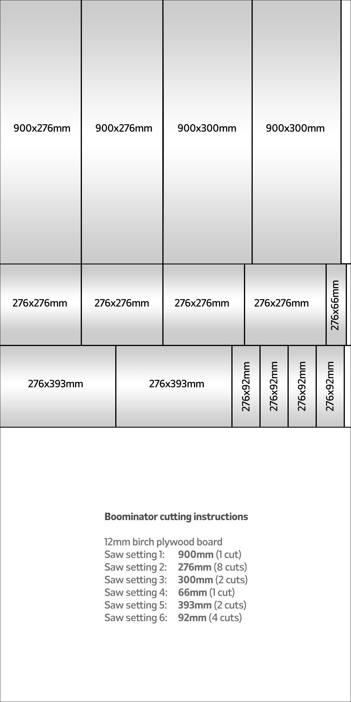
Btw, I forgot to mention. While at the saw, if you can get the left over 900mm bit cut into a few pieces of 132mm length then you can use those for guides to mount the centerbrace. Width of these aren't really important, anything down to about 30mm will work just fine.
@Saturnus can you explain a bit what you mean here ?`
Also do you know what the following parts are used for :
4 x 276 x 92 mm
1 x 276 x 66 mm
I guess 2 of the 276 x 92 mm are used for the port between the brace ?
http://www.diyaudio.com/forums/attachments/class-d/218626d1302873924-boominator-another-stab-ultimate-party-machine-boominator_cuts2.png
how would you guys connect the resistor to the cable ? because i have no soldering iron
Get an soldering iron, seriously that would be the best way to do it.
If not i guess this could be used : Dobbelte samlemuffer | Samlemuffer | Diverse elartikler | Greenline.dk
The volume knob is just a potentiometer. So if you buy a 47k ohm logaritmich potentiometer and put it on your input signal, it'll work. It's been a big advantage to do that for me, because i had alot of distortion, when it played max all the time.I haven't had a AMP6 yet but yes, I also suppose it plays at maximum volume all the time.
@Saturnus can you explain a bit what you mean here ?`
Also do you know what the following parts are used for :
4 x 276 x 92 mm
1 x 276 x 66 mm
I guess 2 of the 276 x 92 mm are used for the port between the brace ?
The 4 x 276 x 92 mm is the port/handle assembly. You only need one of these on each end to be full length though. You can cut the other to fit with the port/handle. But at least one of these on each end must be full length or the end piece will vibrate too much at high volumes.
The 1 x 276 x 66 mm is if you make it as originally intended and you mount it inside the top and inside the electronic compartment and is there to make sure the electronics compartment stays at 66mm width during assembly. You don't need it, it's a very good help though. unless you don't mind it being in there. it's no used permanently either.
Similary the 132mm bit I'm talking about is helper during assembly. 132+12+132mm is 276mm which is the top and bottom pieces. So if you mount the 132mm on the top or bottom, usually top if you assemble it in the correct order then they are just guides to make sure the centerbrace is in the exact middle during assembly. You take them out before you finish.
The volume knob is just a potentiometer. So if you buy a 47k ohm logaritmich potentiometer and put it on your input signal, it'll work. It's been a big advantage to do that for me, because i had alot of distortion, when it played max all the time.
Just note that when it's done like on the Lepai amp, the resistor reacts with the input capacitor and start to both max out and cut bass very high up at about 75%, 3 o'clock position.
The 4 x 276 x 92 mm is the port/handle assembly. You only need one of these on each end to be full length though. You can cut the other to fit with the port/handle. But at least one of these on each end must be full length or the end piece will vibrate too much at high volumes.
An externally hosted image should be here but it was not working when we last tested it.
So you are saying is that you are using 3 pieces of 276x92mm to allign on the 276x276mm sides to figure out where the middle part should be. Is this it ?
The 1 x 276 x 66 mm is if you make it as originally intended and you mount it inside the top and inside the electronic compartment and is there to make sure the electronics compartment stays at 66mm width during assembly. You don't need it, it's a very good help though. unless you don't mind it being in there. it's no used permanently either.
Ok so it's there to make sure you have the correct size of the middle compartment.
Similary the 132mm bit I'm talking about is helper during assembly. 132+12+132mm is 276mm which is the top and bottom pieces. So if you mount the 132mm on the top or bottom, usually top if you assemble it in the correct order then they are just guides to make sure the centerbrace is in the exact middle during assembly. You take them out before you finish.
I guess this is what you mean ?
An externally hosted image should be here but it was not working when we last tested it.
thx for taking the time to explain this.
All correct. Just note that for the port/handle that this has to be 36mm, ie. 3 pieces of ply deep, but only one of the pieces needs to be full length. Which is why only one is show in the sketch-up drawing. I thought it would confuse people if I put both the needed pieces in the drawing without explain that only one needs to be the entire length. The other just needs to be big enough for the hole of the port/handle to fit inside it.
Port size is 3407mm2, defined as 120mm total width and 30mm total height rounded to a 30mm circle in both ends. Length is 35mm, or 3 layered 12mm birchply which actually actual size is 11.65mm.
You wrote this once and together what you say now i am still unsure about the ports. I made a small drawing which might clarify if i understand it correct.
An externally hosted image should be here but it was not working when we last tested it.
Another thing i would like to ask. I have a battery with 14.8V and when it's fully charged and i measure it without load 16.8V which is above the TA2020 chip max voltage. Should i risk and try it ? I am pretty sure the voltage won't be 16.8V with load but i am not sure i would like to risk it or maybe i should use an diode or two to lower the voltage. What is your opinion ?
Another thing i would like to ask. I have a battery with 14.8V and when it's fully charged and i measure it without load 16.8V which is above the TA2020 chip max voltage. Should i risk and try it ? I am pretty sure the voltage won't be 16.8V with load but i am not sure i would like to risk it or maybe i should use an diode or two to lower the voltage. What is your opinion ?
What voltage does the charger charge at?
What voltage does the charger charge at?
Max charge voltage for battery is 16.8V so the charger charges with 16.6V.
Max charge voltage for battery is 16.8V so the charger charges with 16.6V.
I'd throw a nice diode on there, drop the voltage a bit. Won't really affect the sound, and you can use it as polarity protection. If you want to squeeze out the last drop of power from a drained battery, you can put a switch to cut the diode out and get that last volt back
")
Our system is build and playing, and it's DAMM loud (4 Goldwoods), but it seems like the max volume we can play at, before some sort of distortion begins is dependent on which unit we use as input.
Currently I have tried with an iPod Nano 2 Gen, iPhone 4 and my Laptop.
The Nano clearly have the lowest volume and the laptop plays louder than the iPhone.
But for all of them, it seems like they start to distort a little when the player goes up around 80% of the input unit's max volume. Which makes me think that the problem is not the AMP but the input units.
Any idea why this may be, and a solution to fix it?
One thing im not totally sure of is that our Jack cable (3,5) might be to long, i think it's around 5m. Could this be a problem?
But generally speaking, it plays DAMM loud, but would be nice to utilize the system to it's fullest.
Btw. the system is 4 Goldwoods, 4 Piezo's and a AMP6 Basic, which is powered by a Car battery that we have 3 of, where one is for charging cell phones.
Painted with the scotish flag
In advance, thx for the help and see you at Roskilde!
Btw. the system is 4 Goldwoods, 4 Piezo's and a AMP6 Basic, which is powered by a Car battery that we have 3 of, where one is for charging cell phones.
What kind of piezos are you using and what kind of resistors?
Got some of my stuff today
Just wanted to share that i got my 2 x Solar panels today. They are quite big for my taste but hey i knew that already.
Here are some pictures of the panel :
http://dl.dropbox.com/u/3081560/Photo 27-06-11 19.59.50.jpeg
As one can see it's the frame that takes more than 80% of the depth of panel. It's glued with silicone or something similar. I did give it a thought to try to open it but then where should i put it without the frame protecting it hmmmmmm....
My special solar panel switch-mode charger / controller also arrived from Texas Instruments. Here is a pic of it :
I also got my 4 x MPT-001. I have to figure out what resistors to use. I guess i better try couple. Where should i start ? 30ohm and start my way up to let's say 200ohm ?
@saturnus did you have a chance to answer the last question i posted about the port ?
Just wanted to share that i got my 2 x Solar panels today. They are quite big for my taste but hey i knew that already.
Here are some pictures of the panel :
An externally hosted image should be here but it was not working when we last tested it.
http://dl.dropbox.com/u/3081560/Photo 27-06-11 19.59.50.jpeg
An externally hosted image should be here but it was not working when we last tested it.
An externally hosted image should be here but it was not working when we last tested it.
As one can see it's the frame that takes more than 80% of the depth of panel. It's glued with silicone or something similar. I did give it a thought to try to open it but then where should i put it without the frame protecting it hmmmmmm....
My special solar panel switch-mode charger / controller also arrived from Texas Instruments. Here is a pic of it :
An externally hosted image should be here but it was not working when we last tested it.
I also got my 4 x MPT-001. I have to figure out what resistors to use. I guess i better try couple. Where should i start ? 30ohm and start my way up to let's say 200ohm ?
@saturnus did you have a chance to answer the last question i posted about the port ?
- Home
- Amplifiers
- Class D
- The Boominator - another stab at the ultimate party machine