O, btw, the reason I recommend a 100-150 ohm series resistor is that it cut off that first lower frequency bumb of the piezo and only leaves the one at around 5-8KHz. Remember piezos are capacitive loads so a series resistor is a 6 dB/octave highpass filter while a series capacitor acts as an attunator (lowers sensitivity).
When used with the P.Audio drivers it's extremely important to cut that first lower frequency bumb because the woofers actually produce sound very well up to about 4-5 KHz at which point it drops off sharply so you don't want your tweeter to produce any sound under about 4 KHz.
And I might say that it's also primarily for this reason piezo tweeters get a bad rep. Use a 100-150 ohm series resistor on the piezos and use a suitable matching woofer that produce sound to about 4-5 KHz and any piezo tweeter will sound acceptable, high quality piezos will even sound quite good.
Thanks for the tip col, I’ve just signed up. There’s a whole bunch of good info on there. One thing I’m looking for though is a clear description of how to hook up a 3.5mm headphone jack to the inputs of the Amp 9 Basic. I’ve had a search but haven’t seen anything there yet. Do you (or anybody) know of a thread or details somewhere? I am using it for stereo use so will probably connect inputs 1&2 together and to left channel and inputs 3&4 together and to the right channel.
I have been pricing batteries/solar panels etc. To keep costs low and to keep flexibility/simplicity I will make the system 12V. If I find that the amp needs a bit more grunt I will add a 12V to 24V step-up DC-DC converter like the car laptop power supply ones discussed on the 41Hz forum.
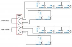
As for hooking up the speakers, if I am using 8 tweeters in total as suggested by anomalous then should my wiring look like this?
I have been pricing batteries/solar panels etc. To keep costs low and to keep flexibility/simplicity I will make the system 12V. If I find that the amp needs a bit more grunt I will add a 12V to 24V step-up DC-DC converter like the car laptop power supply ones discussed on the 41Hz forum.
As for hooking up the speakers, if I am using 8 tweeters in total as suggested by anomalous then should my wiring look like this?
Attachments
looks good to me. Didn't you say you have 4 of the P-audio 10" 4ohm drivers though? Are you only going to use 2 of them?
Don't understand your problem with wiring the 3.5mm jack/socket. It would be the same as wiring RCAs? Once you get your amp9-basic AI there is a circuit diagram that will tell you which pins are positive and which ones are negative.
col.
Don't understand your problem with wiring the 3.5mm jack/socket. It would be the same as wiring RCAs? Once you get your amp9-basic AI there is a circuit diagram that will tell you which pins are positive and which ones are negative.
col.
Hey col, yeah I figured hooking up the headphone jack would be very common and pretty straight forward but I just hadn’t seen a diagram or anywhere showing it yet. I’m sure it will all become very clear once I have the amp 9 in hand.
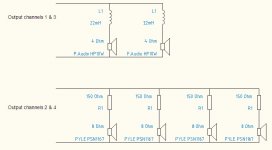
I will be using all 4 P audio drivers and all 8 Pyle piezos. There will be a pair of woofers in each bass reflex enclosure wired as per the above diagram. The two woofers in one enclosure (left channel) will be hooked to output 1 and the other 2 woofers (right channel) to output 3.
I will be using all 4 P audio drivers and all 8 Pyle piezos. There will be a pair of woofers in each bass reflex enclosure wired as per the above diagram. The two woofers in one enclosure (left channel) will be hooked to output 1 and the other 2 woofers (right channel) to output 3.
you only need one resistor for the tweeters.
so for one channel (two sides, two tweeters per side)
---------------[res]-----------o +
| | | |
P P P P
| | | |
--------------------------------o -
heres some pics to show you what i meant about cutting and joining a pair of piezos
a bit messy - but it was a rough cut job with a hand saw just to show you what i meant - normally i use a proper table saw and sled.
150 ohm is much too high for the series resistor.
My understanding is this:
the series resistor does not form a high pass filter - it in fact is a low pass (high pass filters require the cap in series and the resistor in parallel with the load - this is the other way round)
It is a low pass filter designed to prevent high frequency oscillations (100kHz or so) in the amp. the psn 1167's have a capacitance of around .12uF, and the manufacturer recommends a series resistance of 30ohms - this results in a lowpass filter with a corner freq of around 44kHz.
for 4 of these in parallel, the resistor should be about 8 ohms to maintain the same corner freq, and certainly no more than 15 ohms. 150 ohms, with 4 piezos in parallel, gives a low-pass corner freq of about 2.2kHz - definately not what you want.
the series res should be a 10W non-inductive type.
cheers,
ben
ps: the piezos went into the mail today")
so for one channel (two sides, two tweeters per side)
---------------[res]-----------o +
| | | |
P P P P
| | | |
--------------------------------o -
heres some pics to show you what i meant about cutting and joining a pair of piezos
An externally hosted image should be here but it was not working when we last tested it.
An externally hosted image should be here but it was not working when we last tested it.
a bit messy - but it was a rough cut job with a hand saw just to show you what i meant - normally i use a proper table saw and sled.
150 ohm is much too high for the series resistor.
My understanding is this:
the series resistor does not form a high pass filter - it in fact is a low pass (high pass filters require the cap in series and the resistor in parallel with the load - this is the other way round)
It is a low pass filter designed to prevent high frequency oscillations (100kHz or so) in the amp. the psn 1167's have a capacitance of around .12uF, and the manufacturer recommends a series resistance of 30ohms - this results in a lowpass filter with a corner freq of around 44kHz.
for 4 of these in parallel, the resistor should be about 8 ohms to maintain the same corner freq, and certainly no more than 15 ohms. 150 ohms, with 4 piezos in parallel, gives a low-pass corner freq of about 2.2kHz - definately not what you want.
the series res should be a 10W non-inductive type.
cheers,
ben
ps: the piezos went into the mail today
I'm sure the advice given by col and anormalous above is well intended but it's certainly not how I would do it. And I can't guarentee my design will work as intended if it's followed.
In fact I will almost guarentee that you will not have sufficient cooling to the amp9 if you parallel the woofers to 2 ohms and use a 24 volt supply at a later time.
With an amp9 I recommend using each of the outputs to drive one set of speakers, where we define a set of speaker as a woofer and any form of tweeter.
I recommend that with piezo you do not filter the woofers and that you parallel connect the piezos to the woofer with a series resistor. With one piezo between 100 and 150 Ohms and with 2 piezos half that for 47 or 68 Ohms standard values. These resistors need only be 1 Watt types but I recommend the carbon 3 Watt types I use.
I strongly recommend that if you do decide to use piezo that you have plenty of excess wire and that you "face" the woofer terminal plates to face the tweeter cut-outs so that if you want to upgrade to a real tweeter at a later date you can dismount the piezos and fish out the wires to woofer, cut the wire and insert a real x-over filter. I just glued the filter component directly to the tweeter horm but note that the proximity to the magnet will affect the inductor so you need to get a multimeter that can measure inductor values to get it completely accurate.
<shrugs> try both, see how they sound. pick what sounds best.
for reference:
Low Pass Filter and High Pass Filter theory.
or wikipedia even
which of these pictures looks like a resistor in series with a capacitive load?
for first order high and low pass RC filters:
cutoff freq in Hz = 1/(2*pi*R*C)
plug the values in and come to your own conclusions.
Col has built a lot of these 41Hz amps, and regularly runs small events with them.
In the spirit of the scientific method, try both configurations and see what works best. your finger on the heatsink is the best measure of whether you have sufficient cooling. report your findings so we can all benefit and mistakes arent replicated.
for my part, i'm quite happy to be shown i'm mistaken - so I'll set up my speaker testing rig and get some some real world response curve measurements on the piezos using a range of resistor values, and then we will have some hard data.
cheers,
Ben
Thanks for all the help guys.
Saturnus – noted, will definitely mount the woofers so that the tabs face the tweeter cut out and wire any crossover components to be accessible at a later time.
But as for the crossover components... hey I’m willing do some testing and give some feedback if it will help. I’ve attached 2 jpegs showing the two different configurations as described by Saturnus and anomalous/col. Can you guys take a quick check and make sure that is what you described?
Any luck with the crashed hard disk Saturnus?
Attachments
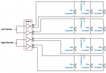
I prefer the first setup diagram. Also, with that one you can use a car rear/front fader to adjust the level between the woofers/piezo. This will also deal with your jack to RCA input dilemma. Iv'e used one of these for a few gigs and it works well. see jaycar CAT. NO. AA0485
http://jaycar.com.au/ShowLargephoto.asp?id=57&IMAGE=
The first amp9 I built I put a fan on the heatsink. I don't think it was needed though.
On the second amp I built I used a heatsink off of a Pentium II, It runs very cool, even flat out. I have a spare one if you are interested?
http://pix.minirig.org.au/main.php?g2_itemId=805
col.
I agree with col (strangely enough).
what he says about surplus CPU heatsinks is good - i use them all the time as well. i often get given bung computers, and the heatsinks are good salvage. more recent cpu's often have fantastic copper cored monsters - incredibly efficient for their size.
Here is a pic of some that i have. I think the blue one is similar to what col is talking about.
An externally hosted image should be here but it was not working when we last tested it.
The problem is that amp is inside the case with very little air coming in or out, and when you leave it out in the midday sun playing the amp case can become extremely hot. My guess is around 80 degrees celcius without having taking measurements. That's coming dangerously close to the termal envelope of many of the other components. And that's with an amp6basic.
I guess you could use a fan that only comes on when charging but you'll need extra circuitry for that. And everything extra means something more that can go wrong.
I guess you could use a fan that only comes on when charging but you'll need extra circuitry for that. And everything extra means something more that can go wrong.
i came in late on this thread, so forgive me if ive missed something. Saturnus, is the whole box a single chamber, or is it split in the middle?
i agree with you - mounting the amp modules inside may well result in heat issues.
I'd be tempted to mount them on a bit of 4mm aluminium plate which could be screwed (just like a plate amp ) into a recessed cutout on the box somewhere and if need be bolt some low profile heatsinks to the outside.
cheers,
ben
i agree with you - mounting the amp modules inside may well result in heat issues.
I'd be tempted to mount them on a bit of 4mm aluminium plate which could be screwed (just like a plate amp
) into a recessed cutout on the box somewhere and if need be bolt some low profile heatsinks to the outside.cheers,
ben
It's 3 separate chambers actually. A left and a right speaker enclosure. And a middle enclosure for batteries and electronics.
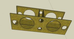
I gotten the CAD files. Unfortunately not all could be recreated.
The thing to note is the 160mm wide 3mm deep grooves routed in the both sides of the middle compartment. They allow for the battery to slide in from the bottom because it becomes 66mm wide at that place but doesn't allow for the battery to slide around at all since they are 65mm wide and 150mm long (and about 200mm high when 2 are stacked on top of eachother).
I use a G111 case from Velleman. It's 65mm wide same as the batteries and 55mm high and 115mm long. The case is an aluminium case so it function perfectly as a heatsink as well, and the internal built-in PCB stand-offs fits the holes from the amp6basic perfectly. I use the remaining space on either side to hold cables, chargers (both battery and iPod charger) and the iPod itself. So there's no much left over room for cooling.
Attachments
- Home
- Amplifiers
- Class D
- The Boominator - another stab at the ultimate party machine