No. An SLA charger measures the battery while charging. Putting it in front of the solar charger will make it unable to detect the battery so it won't turn on.
A solar charger just needs a DC supply of sufficient voltage. You can probably find dirt cheap second hand laptop supplies on ebay.
Thanks Saturnus. You recommended a regulated supply of 15V, although gmarsh mentioned that he's using 19V.
Can a 19V or 20V laptop power supply be used, directly connected to the solar charge controller?
Thanks Saturnus. You recommended a regulated supply of 15V, although gmarsh mentioned that he's using 19V.
Can a 19V or 20V laptop power supply be used, directly connected to the solar charge controller?
I think I recommend minimum 15V. Solar panels can reach 22V open voltage, so anything between those.
I think I recommend minimum 15V. Solar panels can reach 22V open voltage, so anything between those.
Excellent! Thanks again... I think the IT support guys at work have some spare laptop power supplies... now gotta get all the 'ingredients' ready to build the Boominator Mini...
Anyone?Hey guys.
I've been thinking about buying a couple of Neutrik NTE4 for my halfinator, but how do i wire them up with my AMP6?
I've attached a photo of how i think it should be wired
Correct me if im wrong.
Hey guys.
I've been thinking about buying a couple of Neutrik NTE4 for my halfinator, but how do i wire them up with my AMP6?
I've attached a photo of how i think it should be wired
Correct me if im wrong.
Bad move.
It's a step-up transformer for microphones. An MP3 player would cause the amp to see too many volts on the input, and you may well saturate the transformer, giving lots of distortion.
An interstage transformer here isn't necessary, I don't understand why you think it might be needed.
Chris
Well, the halfinator aren't that loud when using the ipod. When i use the computer it can play louder. A guy has mentioned the NTE4 as a good booster in the boominator page at facebook. He said that the sound didn't distort. I dont want to make i 4 times louder, just double maybe, via a potmeter.Bad move.
It's a step-up transformer for microphones. An MP3 player would cause the amp to see too many volts on the input, and you may well saturate the transformer, giving lots of distortion.
An interstage transformer here isn't necessary, I don't understand why you think it might be needed.
Chris
Or at least give it a try.
Well, the halfinator aren't that loud when using the ipod. When i use the computer it can play louder. A guy has mentioned the NTE4 as a good booster in the boominator page at facebook. He said that the sound didn't distort. I dont want to make i 4 times louder, just double maybe, via a potmeter.
Or at least give it a try.
Just replace the feedback resistor to a higher value instead. Much easier.
On the amp6? Mine is 82K what would happen if i put in a 160K og even more?Just replace the feedback resistor to a higher value instead. Much easier.
On the amp6? Mine is 82K what would happen if i put in a 160K og even more?
Try 100K first
ok, i will try that. Do you have an idea of the result?Try 100K first
one like this http://www.el-supply.dk/?Gid=52&VNr=066100 ? or how many watt, % etc. should it be?
Last edited:
Still waiting for my amp6 sneaky's, and in the meantime I'm contemplating the power circuits again ")
This is my power and panel circuit:

I think these will be my final questions on this.
Q1. Will the batteries go flat if the 12v smart charger is permanently attached to the batteries, but with the charger NOT turned on?
Q2. Can I make a simple circuit at the 12v input socket so I can use either of a or b.
a. an external 12v battery
b. any external DC power source (12v - 19v or so ie a 12v power pack or a laptop powerpack) etc)/
or don't worry about it and just have the external dc socket for 12v only.
S.
This is my power and panel circuit:
I think these will be my final questions on this.
Q1. Will the batteries go flat if the 12v smart charger is permanently attached to the batteries, but with the charger NOT turned on?
Q2. Can I make a simple circuit at the 12v input socket so I can use either of a or b.
a. an external 12v battery
b. any external DC power source (12v - 19v or so ie a 12v power pack or a laptop powerpack) etc)/
or don't worry about it and just have the external dc socket for 12v only.
S.
ok, i will try that. Do you have an idea of the result?
one like this 1% 100K OHM METALFILM MODSTAND ? or how many watt, % etc. should it be?
Gain = Rfb/Rin, so if you have 82K feedback and 22K input it's x3.73 (+11.4dB). With 100K feedback it becomes x4.55 (+13.2dB). You can also change the input resistor instead. And it might actually be easier as that's farther from the chip. If you change that to 15K and keep the 82K feedback then it's x5.47 (+14.8dB).
Regardless of what method. Do not go above x5.62 (+15dB). If your source cannot drive the amp to clipping with this gain then your source is too weak to fully power a TA2020 chip and you have to use a preamp. I doubt it will be a problem as in the last setup (15K Rin/82K Rfb) it is enough for the 2 weakest output mp3 player ever mass produced that I know of, ie. the Ipod nano 3rd Gen (the fat boy) and the Sony Walkman MP3.
Those resistors you linked are actually too large, in physical size. The amp6 uses half-size resistors. Both 15K and 100K linked below. It's Vishay resistors, commonly known as probably the best there is. And being resistors, they're dirt cheap.
Resistor 0204 0,4W 1% 15K Taped Elektronik Lavpris ApS
Resistor 0204 0,4W 1% 100K Taped Elektronik Lavpris ApS
I think these will be my final questions on this.
Q1. Will the batteries go flat if the 12v smart charger is permanently attached to the batteries, but with the charger NOT turned on?
Q2. Can I make a simple circuit at the 12v input socket so I can use either of a or b.
a. an external 12v battery
b. any external DC power source (12v - 19v or so ie a 12v power pack or a laptop powerpack) etc)/
or don't worry about it and just have the external dc socket for 12v only.
S.
1) Depends on the charger. I would not unless the charger user manual or the manufacturer specifically tells you that you can. You can however insert a switch on the power line (warnings of high voltage and all that) that connects the charger to the battery when the charger is connected to AC power.
2a) The socket would require a (break-before-make) switch that disconnects the internal batteries before the external batteries are connected.
2b) 19V is obviously far too much for the amp6. Maximum voltage should be 15V. Obviously this requires the same switch as in 2a above so that the internal batteries are disconnected from the system.
okay, so if i change the feedbacks then both R5 and R6 and if i change the input resistors then its R4 and R2Gain = Rfb/Rin, so if you have 82K feedback and 22K input it's x3.73 (+11.4dB). With 100K feedback it becomes x4.55 (+13.2dB). You can also change the input resistor instead. And it might actually be easier as that's farther from the chip. If you change that to 15K and keep the 82K feedback then it's x5.47 (+14.8dB).
Regardless of what method. Do not go above x5.62 (+15dB). If your source cannot drive the amp to clipping with this gain then your source is too weak to fully power a TA2020 chip and you have to use a preamp. I doubt it will be a problem as in the last setup (15K Rin/82K Rfb) it is enough for the 2 weakest output mp3 player ever mass produced that I know of, ie. the Ipod nano 3rd Gen (the fat boy) and the Sony Walkman MP3.
Those resistors you linked are actually too large, in physical size. The amp6 uses half-size resistors. Both 15K and 100K linked below. It's Vishay resistors, commonly known as probably the best there is. And being resistors, they're dirt cheap.
Resistor 0204 0,4W 1% 15K Taped Elektronik Lavpris ApS
Resistor 0204 0,4W 1% 100K Taped Elektronik Lavpris ApS
Still trying to design my enclosure and i have a few questions.
1.WinISD have something called "1st port resonance" in the vents tab. What is this and do I need to consider it?
2.Boxnotes have something so many "wall resonance" values, for example: box top to bottom resonance 254Hz, should i ignore these? If not, how should I use them in my calculations?
3. A formula for calculating the box tuning frequncy manually would be great, I havent found any.
Some questions.
Hey so I have some questions..
They've probably been answered but hey I've looked and can't find the answers -when's that step-by-step guide coming out anyway?
Do I need to round BOTH sides of the speaker holes and both sides of the handle ports? With what size router bit?
What is the model of the Amp6b enclosure that can be used as it's own heat sink? (US vendors preferred)
Is it suggested to seal the piezos with silicone to the wood like the woofers?
Last - I saw a post where Saturnus explained why the tweeters should be mounted centered like the woofers and not in the corners like some builders have done. I intuitively feel that the corners would be a better place to mount them because the boombox will be on the ground most of the time and the closer the speakers are to the ground the more sound will be absorbed, especially high frequencies. Plus the piezos displace VERY little air, if any, so I can't see how air flow/pressure would interfere with the woofers. What's the deal?
Hey so I have some questions..
1) There's so many pictures on the facebook page it pretty much equals a step by step guide.
2) The outside of the baffle. Both sides of the port. 1/2" roundover tool.
3) Hammond 1590N1 (alternatively black and/or flanged lid as desired). Available anywhere in the world.
4) Yes
5) Putting it in the corner raises the output of the piezo in the exact frequency range where it performs the worst, ie. is most the "piezo-ie".
Nice thanks for the answers. How exactly does the placement raise the output? I know you posted about it in the past but I am interested. What is the name of this concept so I may satisfy my curiosity?
My boominator design...
Hey Guys!
I just recently finished my (modified) boominator build!! And since I got so much tips and inspiration from this forum, I wanted to just give something back by reporting on the build, the problems I experienced, etc. so that other ppl will have an easier time...
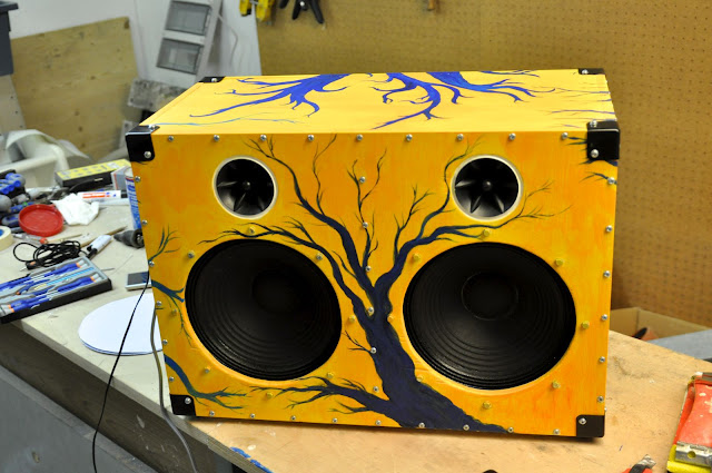
so, first a pic on the finished "masterpiece"
If you are just interested in more pictures from the build, follow this link:
https://picasaweb.google.com/100780868841767618460/ModifiedBoominatorBuild#
DESIGN:
As you can see, its quiet modified. I made it more compact, by
(1) leaving out the middle battery compartment from the original design and (2) turning the two cabinets by 90deg.
All the internal dimensions (heigth, with, depth) stayed the same, so that the accoustical properties should be similar to the original Boominator.
I used a more massive piece of plywood to seperate the two channels (24mm thickness). This is to make sure left and right channel dont influence each other. I dont know if its necessary, but the product sounds good.
Since it has no battery, its basically a set of efficient active boxes, and it needs an external power supply. I did this because of two reasons:
(1) so I can be a bit more flexible in usage - I can just hook it up to a regular 12v power adapter if Im indoors, the 12v car plug if Im around a car, A solar panel directly (more on that later), or a external solar panel/battery connection and
(2) the design gets a lot more compact and easier to transport.
SKETCHES
So lets get down to work: This is a sketch of the design...
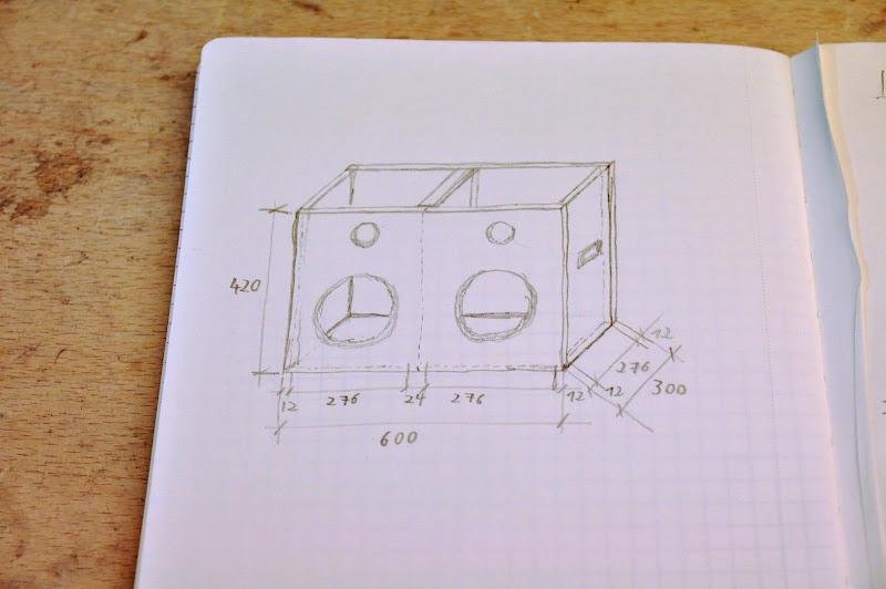

and acording to that I had the 12mm birch plywood pieces cut already to the right dimensions.
COMPONENTS
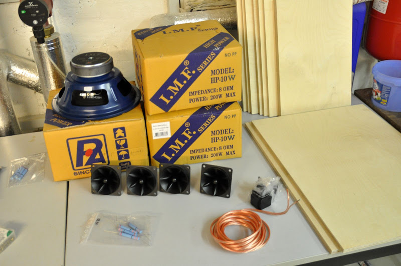
I used the standard boominator components
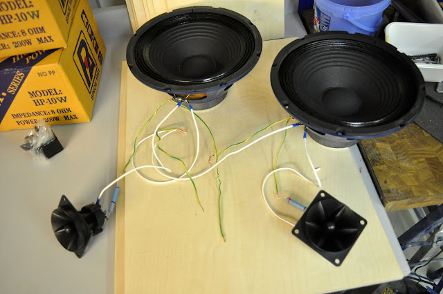
- 4x P.Audio HP-10W
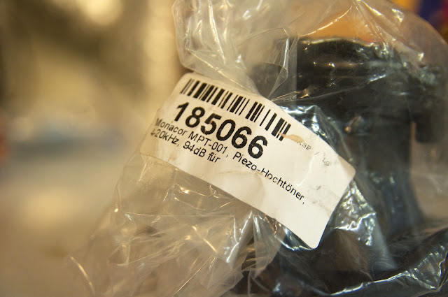
- 4x Monacor MPT-001 Tweeters (cheap replicas, but I couldnt get the original motorolas...)
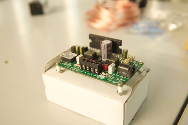
- 1x Amp6-Basic amplifier, pre-assembled (yes, Im lazy... ;D )
- Pretty thick audio cable
- 4x 36 and 4x 47 ohm resistors if I remember correctly (to try out the difference), 10W (Grossely over-dimensioned I think )
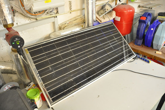
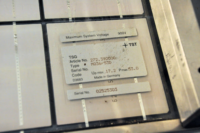
- a 15year old, used 53Wp solar panel (if used with a battery it would also be extremely oversized, but I had it lying around in the basement... ). Maximum voltage with no load is 17,2v
BUILDING
STEP 1: Checking the components
I started off by checking if all ordered component worked. I used my amp6 with a 12v adapter, each channel seperately.
STEP 2: Woodwork
As I said already, I used 12mm birch plywood for everything,except for the panel seperating left and right channel - there I used 24mm for additional insulation. You can get the pieces cut from your hardware store or carpenter, and for some extras you can get it cut exactly into the dimensions you want. its was a neat option for me, since I didnt have the tools to cut them myself with the required accuracy of +/- 1mm.
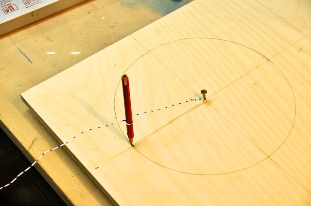
I started of cutting the holes in the frontpanels - since I didnt have the perfect tools, I used an improvised circle and Jigsaw.
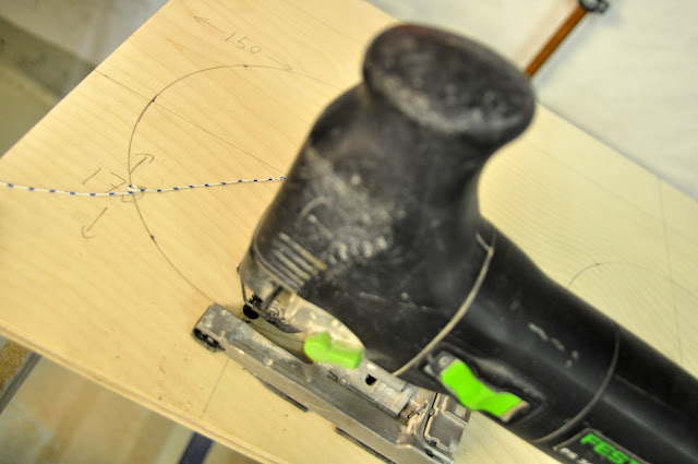
One note on using a Jig-saw: You should use a fresh blade. and make sure that the front-side (the one that is supposed to have a nice, clear cut) is on the bottom when you cut. On the top-side some peaces of the first layer of the ply-wood will eventually come off a little bit...
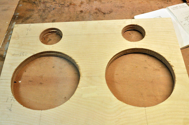
For the tweeters, I used a core-drill. Its diameter was slightly bigger than the tweeter, but I filled it up with Polymer-glue afterwards. And it actually looks quite good
For the sidepanel-handles, I drilled two round holes with the right diameter on the sides, and connected it with a jig saw.

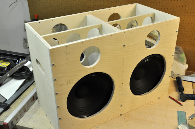
Since the middle-pieces between the tweeters, as well as the 24mm panel between left and right side have no holes, I could stack it together the first time:

Note that the sidepannels width fits exactly the 2 x heigth of the speakers + the 12mm plywood middlepiece. Originally the speakers should be mounted directly back-to-back (with a big hole in the wood-pieces in between). But that means that you would have to add 6mm of some material (e.g. a gasket, or just a ring of 6mm wood) on both sides between the inside of the frontpanel and the frontside of the driver. This is a fact that wasnt clear to me until that point, so I want to stress it here for future builders
Since I couldnt find a fitting 6mm wood-piece, I just left the wood-panel in the middle, knowingly sacrificing a bit of effciency of the drivers, but keeping the increased structural stability of the design.
Next i pre-drilled about one-million skrew holes (I like the optics) and perforated the middle-sheet with the same wood-core drill that I used for the tweeter-holes, and put it together temporarily
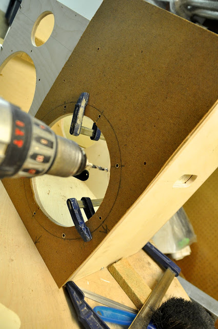
Next step is to drill the holes with which I fixed the drivers to the cabinet.
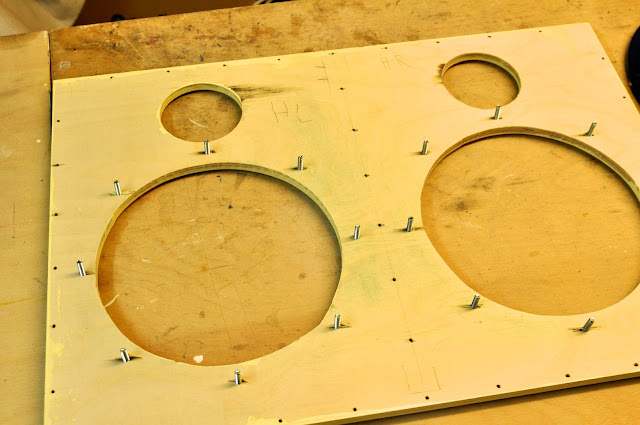
For this I first created a gauge from a thin woodfibreboard, that I used later to drill the holes in the cabinet. Note that the holes really need to fit exactly, else the skrews wont fit.
Now we have all seperate wood pieces ready for putting together. this is the perfect time to smoothen all the surfaces and edges with fine sand paper. Afterwards I already applied a baselayer of paint, since at this point its easy to handle all the different bits and pieces seperately.
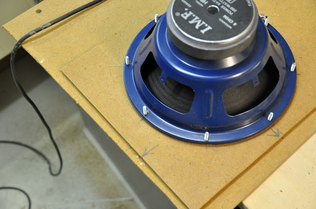
STEP 3: Prepare Audio Parts
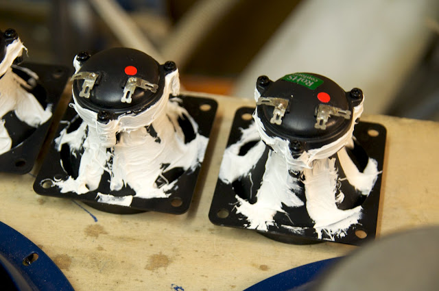
we first have to prepare drivers and tweeters. From the drivers, we have to remove the lable, so that the glue will stick nicely:

For the Tweeters it seems to be beneficial for the sound-quality if you fill the grooves with acryl or something similar (I used a polymer-glue, that I also used for all other gluing- or sealing purposes).
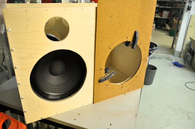
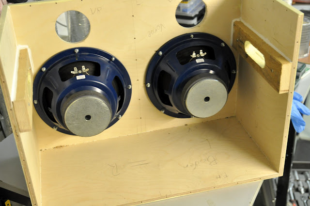
STEP 4: Put it all together
First I put together one front-panel, the bottom and the two side panels with polymer glue and some screws. I also mounted the internal handle-pieces in place. Than I mounted the drivers.
Next I have to fit the panel for the audio-jack and the power supply.

For This I needed to get the jig-saw out again...

mounted and sealed this looks like this:

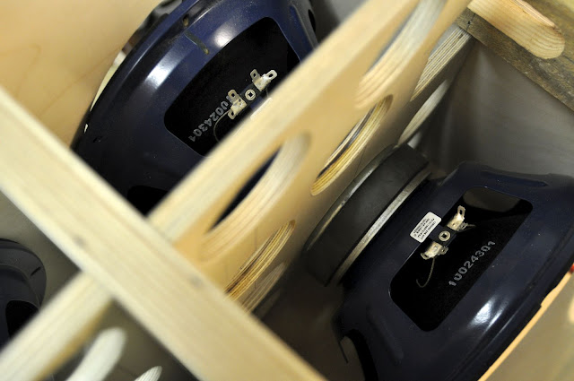
Next you put the middle panel between the drivers in place. If you decide to mount them really back-to-back, you should use 2-component iron glue. I glued the drivers to the middle panel with polymer glue.
Next I mounted the other two drivers to the second front panel, put sufficient glue on the middlepanel (for the driver-backsides) and screwed it all together. Its important to make sure that the middle panels stay exactly in place.
Unfortunately I dont have pics from these steps, only after finishing the wiring:

STEP 5: WIRING:
There is enough circuit diagrams around on this forum. In my design i mounted the amp on the middle-board, without an extra cooler for the chip (I hope this wont be a problem later, but so far the chip always stayed really cold).
Originally I mounted audio-jack and power supply on one metal panel. However, this turned out to be a really bad idea, so I can now advise you: always seperat audio signal from power supply!! I put it on the same input panel (that was made of metal), and even if the connections were insulated, I still got a pretty strong disturbance signal - a relatively loud "brrrr" when I played music.
When I used an audio cable and connected it to the amp6 directly,the problem disapeared. Now I have a cable hanging out of the handle-hole. I dont really like that solution, but it works.
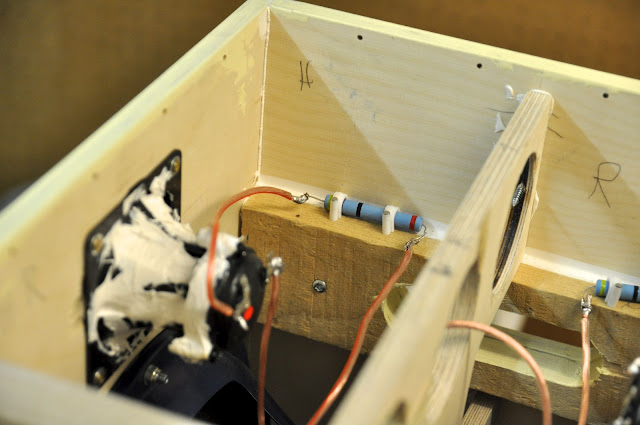
To connect the drivers in the second channel, I drilled a hole, put the wires through, and sealed it with polymer glue afterwards.
I carefully soldered al contacts, and fixed the resistor in the cabinet so it wouldnt fly around loosely
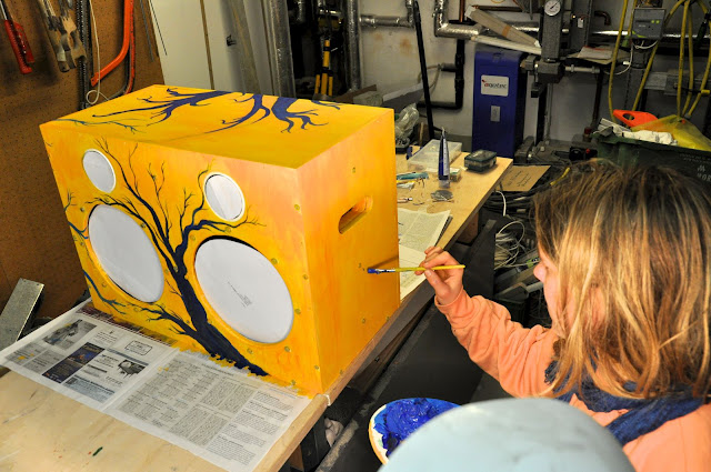
and, last but not least: PAINTING
here I got a little support by my artistic friend. First a yellow layer with acrylic paint (as used for artistic paintings), and blue for the motive. At the end I applied 3 layers of transparent laquer for protection.
After drying you can mount the edges, and - tadaa - your new boominator!
Hey Guys!
I just recently finished my (modified) boominator build!!
And since I got so much tips and inspiration from this forum, I wanted to just give something back by reporting on the build, the problems I experienced, etc. so that other ppl will have an easier time...so, first a pic on the finished "masterpiece"
If you are just interested in more pictures from the build, follow this link:
https://picasaweb.google.com/100780868841767618460/ModifiedBoominatorBuild#
DESIGN:
As you can see, its quiet modified. I made it more compact, by
(1) leaving out the middle battery compartment from the original design and (2) turning the two cabinets by 90deg.
All the internal dimensions (heigth, with, depth) stayed the same, so that the accoustical properties should be similar to the original Boominator.
I used a more massive piece of plywood to seperate the two channels (24mm thickness). This is to make sure left and right channel dont influence each other. I dont know if its necessary, but the product sounds good.
Since it has no battery, its basically a set of efficient active boxes, and it needs an external power supply. I did this because of two reasons:
(1) so I can be a bit more flexible in usage - I can just hook it up to a regular 12v power adapter if Im indoors, the 12v car plug if Im around a car, A solar panel directly (more on that later), or a external solar panel/battery connection and
(2) the design gets a lot more compact and easier to transport.
SKETCHES
So lets get down to work: This is a sketch of the design...
and acording to that I had the 12mm birch plywood pieces cut already to the right dimensions.
COMPONENTS
I used the standard boominator components
- 4x P.Audio HP-10W
- 4x Monacor MPT-001 Tweeters (cheap replicas, but I couldnt get the original motorolas...)
- 1x Amp6-Basic amplifier, pre-assembled (yes, Im lazy... ;D )
- Pretty thick audio cable
- 4x 36 and 4x 47 ohm resistors if I remember correctly (to try out the difference), 10W (Grossely over-dimensioned I think
)- a 15year old, used 53Wp solar panel (if used with a battery it would also be extremely oversized, but I had it lying around in the basement... ). Maximum voltage with no load is 17,2v
BUILDING
STEP 1: Checking the components
I started off by checking if all ordered component worked. I used my amp6 with a 12v adapter, each channel seperately.
STEP 2: Woodwork
As I said already, I used 12mm birch plywood for everything,except for the panel seperating left and right channel - there I used 24mm for additional insulation. You can get the pieces cut from your hardware store or carpenter, and for some extras you can get it cut exactly into the dimensions you want. its was a neat option for me, since I didnt have the tools to cut them myself with the required accuracy of +/- 1mm.
I started of cutting the holes in the frontpanels - since I didnt have the perfect tools, I used an improvised circle and Jigsaw.
One note on using a Jig-saw: You should use a fresh blade. and make sure that the front-side (the one that is supposed to have a nice, clear cut) is on the bottom when you cut. On the top-side some peaces of the first layer of the ply-wood will eventually come off a little bit...
For the tweeters, I used a core-drill. Its diameter was slightly bigger than the tweeter, but I filled it up with Polymer-glue afterwards. And it actually looks quite good
For the sidepanel-handles, I drilled two round holes with the right diameter on the sides, and connected it with a jig saw.
Since the middle-pieces between the tweeters, as well as the 24mm panel between left and right side have no holes, I could stack it together the first time:
Note that the sidepannels width fits exactly the 2 x heigth of the speakers + the 12mm plywood middlepiece. Originally the speakers should be mounted directly back-to-back (with a big hole in the wood-pieces in between). But that means that you would have to add 6mm of some material (e.g. a gasket, or just a ring of 6mm wood) on both sides between the inside of the frontpanel and the frontside of the driver. This is a fact that wasnt clear to me until that point, so I want to stress it here for future builders
Since I couldnt find a fitting 6mm wood-piece, I just left the wood-panel in the middle, knowingly sacrificing a bit of effciency of the drivers, but keeping the increased structural stability of the design.
Next i pre-drilled about one-million skrew holes (I like the optics) and perforated the middle-sheet with the same wood-core drill that I used for the tweeter-holes, and put it together temporarily
Next step is to drill the holes with which I fixed the drivers to the cabinet.
For this I first created a gauge from a thin woodfibreboard, that I used later to drill the holes in the cabinet. Note that the holes really need to fit exactly, else the skrews wont fit.
Now we have all seperate wood pieces ready for putting together. this is the perfect time to smoothen all the surfaces and edges with fine sand paper. Afterwards I already applied a baselayer of paint, since at this point its easy to handle all the different bits and pieces seperately.
STEP 3: Prepare Audio Parts
we first have to prepare drivers and tweeters. From the drivers, we have to remove the lable, so that the glue will stick nicely:
For the Tweeters it seems to be beneficial for the sound-quality if you fill the grooves with acryl or something similar (I used a polymer-glue, that I also used for all other gluing- or sealing purposes).
STEP 4: Put it all together
First I put together one front-panel, the bottom and the two side panels with polymer glue and some screws. I also mounted the internal handle-pieces in place. Than I mounted the drivers.
Next I have to fit the panel for the audio-jack and the power supply.
For This I needed to get the jig-saw out again...
mounted and sealed this looks like this:
Next you put the middle panel between the drivers in place. If you decide to mount them really back-to-back, you should use 2-component iron glue. I glued the drivers to the middle panel with polymer glue.
Next I mounted the other two drivers to the second front panel, put sufficient glue on the middlepanel (for the driver-backsides) and screwed it all together. Its important to make sure that the middle panels stay exactly in place.
Unfortunately I dont have pics from these steps, only after finishing the wiring:
STEP 5: WIRING:
There is enough circuit diagrams around on this forum. In my design i mounted the amp on the middle-board, without an extra cooler for the chip (I hope this wont be a problem later, but so far the chip always stayed really cold).
Originally I mounted audio-jack and power supply on one metal panel. However, this turned out to be a really bad idea, so I can now advise you: always seperat audio signal from power supply!! I put it on the same input panel (that was made of metal), and even if the connections were insulated, I still got a pretty strong disturbance signal - a relatively loud "brrrr" when I played music.
When I used an audio cable and connected it to the amp6 directly,the problem disapeared. Now I have a cable hanging out of the handle-hole. I dont really like that solution, but it works.
To connect the drivers in the second channel, I drilled a hole, put the wires through, and sealed it with polymer glue afterwards.
I carefully soldered al contacts, and fixed the resistor in the cabinet so it wouldnt fly around loosely
and, last but not least: PAINTING
here I got a little support by my artistic friend. First a yellow layer with acrylic paint (as used for artistic paintings), and blue for the motive. At the end I applied 3 layers of transparent laquer for protection.
After drying you can mount the edges, and - tadaa - your new boominator!
- Home
- Amplifiers
- Class D
- The Boominator - another stab at the ultimate party machine