I received speakers (HP10W), piezos (MPT-001), grills, and a lot of small things(cables and so on..). Wired it all up, and everything works. But the piezos where way to significant. But that's because i havent received my resistors yet(Tip: they are very cheap from Ebay).
I need to be a bit of a planning-freak, as i can only loan a workshop for a weekend.
I need some good ideas for making the midder compartment accessible. My idea was a hinge, so i could open the front-end of the middercompartment?
I need to be a bit of a planning-freak, as i can only loan a workshop for a weekend.
Im not quite sure what is meant here. The drivers has some pretty firm foam on the edges. When they are glued and screwed to the cabinet it should be airtight. Where and why should i apply silicone sealant afterwards?I think there's been a misunderstanding here. I didn't say glue the grill to neither the cabinet nor the driver. Instead you use a thick layer of glue on both the cabinet and the driver and wait until they're glue-ready as per instructions for the specific glue you use. Then you just pop the grill in between the two without the rubber band, and compress lightly or as needed by the glue instructions. After hardening, remove compression and allow the foam surround of the driver to reset before using sealer around the driver.
I need some good ideas for making the midder compartment accessible. My idea was a hinge, so i could open the front-end of the middercompartment?
You "glue" the drivers with the sealant and just use plenty of it. That way the sealant goes through the grill holes as well and glues the whole thing together. Sealant is a quite good glue especially for this since it has give meaning it can withstand vibrations far better than regular glue, and it's much more effective sealant than glue. It is of outmost importance that there's not even a tiny hole that shouldn't be there.
Thanks for your quick reply. I'm pretty much as ready as i can get, just need to get some plywood and start building.You "glue" the drivers with the sealant and just use plenty of it. That way the sealant goes through the grill holes as well and glues the whole thing together. Sealant is a quite good glue especially for this since it has give meaning it can withstand vibrations far better than regular glue, and it's much more effective sealant than glue. It is of outmost importance that there's not even a tiny hole that shouldn't be there.
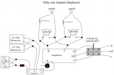
If anybody needs help with some wiring, i made a diagram that should help a little
")
Attachments
I'm looking for a VU-meter for my boominator... Has anyone found a suitable solution?
I've found this one: FA103: WIRE LESS V.U. METER 15 LED SOUND DETECTOR LEVEL MIC CIRCUIT KIT | eBay
I'll then avoid to mount the 15 LED's, and insted connect my own LED's.
My concern here is, that I suppose the VU-meter outputs 2V to the LED's, but I need 12V, as my LED's are connected in series.
Can anyone tell me if it would be possible to mod this VU-meter, so it outputs 12V to the LED's?
Schematics are found here: http://www.apelectronics.co.za/Stores/toptronic/ArticleImages/FK103E-1.PDF
I'm looking for a VU-meter for my boominator... Has anyone found a suitable solution?
I've found this one: FA103: WIRE LESS V.U. METER 15 LED SOUND DETECTOR LEVEL MIC CIRCUIT KIT | eBay
I'll then avoid to mount the 15 LED's, and insted connect my own LED's.
My concern here is, that I suppose the VU-meter outputs 2V to the LED's, but I need 12V, as my LED's are connected in series.
Can anyone tell me if it would be possible to mod this VU-meter, so it outputs 12V to the LED's?
Schematics are found here: http://www.apelectronics.co.za/Stores/toptronic/ArticleImages/FK103E-1.PDF
Each 2 LEDs are connected to 12 V, so you will just have to put some more LEDs in series and use a smaller resistor. Make sure that that the forward voltage drops doesn't exceed the supply. If you want more LEDs, then just put them in parallel on each branch with the transistor.
Last edited:
I need some good ideas for making the midder compartment accessible. My idea was a hinge, so i could open the front-end of the middercompartment?
We created a drawer to hold everything. We could pull it out and access the amp, batteries, cables, switches etc very easily this way. It was of course more complex to build, but we are extremely happy with it compared to our earlier boominator builds without a drawer. The drawer would only have to be connected with one speaker cable to each of the two speaker compartments, so that makes it easy to remove and plug in.
I'm looking for a VU-meter for my boominator... Has anyone found a suitable solution?
I've found this one: FA103: WIRE LESS V.U. METER 15 LED SOUND DETECTOR LEVEL MIC CIRCUIT KIT | eBay
I'll then avoid to mount the 15 LED's, and insted connect my own LED's.
My concern here is, that I suppose the VU-meter outputs 2V to the LED's, but I need 12V, as my LED's are connected in series.
Can anyone tell me if it would be possible to mod this VU-meter, so it outputs 12V to the LED's?
Schematics are found here: http://www.apelectronics.co.za/Stores/toptronic/ArticleImages/FK103E-1.PDF
You might wanna check out this build.. He made a giant VU meter..
The “Malen” Boombox « Popdevelop – A developer team from Malmö, Sweden
is there any news on the 41hz sign up for the shop?
i need to order the amp6-b as soon as possible, or would you recommend that i should just buy the MKll Tripath TA2024 from ebay?..
or is it possible that someone who already has an account can buy it for me somehow?
im from Denmark
i need to order the amp6-b as soon as possible, or would you recommend that i should just buy the MKll Tripath TA2024 from ebay?..
or is it possible that someone who already has an account can buy it for me somehow?
im from Denmark
is there any news on the 41hz sign up for the shop?
i need to order the amp6-b as soon as possible, or would you recommend that i should just buy the MKll Tripath TA2024 from ebay?..
or is it possible that someone who already has an account can buy it for me somehow?
im from Denmark
No news.. 41hz aren't answering any of the many Q's in the forum at 41hz.com
I would really also love to buy one through another dane???
That cant have left much space for batteries? You must have made the elextronics compartment longer than the sketchup drawing.We created a drawer to hold everything. We could pull it out and access the amp, batteries, cables, switches etc very easily this way. It was of course more complex to build, but we are extremely happy with it compared to our earlier boominator builds without a drawer. The drawer would only have to be connected with one speaker cable to each of the two speaker compartments, so that makes it easy to remove and plug in.
Actually i think i will consider doing that. I found a (LxWxH) 181x77x167 sized 20AH battery that could fit then which would make the Boominator a couple of kilos heavier, but then im not as dependent on sun
You might wanna check out this build.. He made a giant VU meter..
The “Malen” Boombox « Popdevelop – A developer team from Malmö, Sweden
Yeah, I've seen that, but its seems way too complicated compared to my electronics skills
- but I've found a suitable solution that I think will be great - pictures will be posted ofcourse Each 2 LEDs are connected to 12 V, so you will just have to put some more LEDs in series and use a smaller resistor. Make sure that that the forward voltage drops doesn't exceed the supply. If you want more LEDs, then just put them in parallel on each branch with the transistor.
Ahh, of course, I see that now
Thanks for opening my eyes ;-)Hi everyone, I'm new here. I'm also on the Dutch 'boominator' topic, called 'kistradio' topic. I'm building a boominator and I'm stuck with a few questions. But first, some pictures of the idea of my boominator. Disign picture 1, design picture 2, schematic. The schematic is in Dutch, so I don't think you'll understand most of it.. In my box, there's going to be one subwoofer (Visaton W170S) and two car-speakers (Blaupunkt GTx-542). It's all powered by a 12V battery and it can switch to power supply (12V). I'm also going to add two LED VU meters. Later on, I maybe add a Raspberry Pi to my speaker.
I've got one question about the speaker. I want to add a simple bass/treble controllers based on a NE5532 opamp. There are lots of schematics on the internet about bass/treble controllers, but since I've got only a 12V power supply, it's not simple to build a controller. I have already found a schematic which makes a symmetric power supply out of my battery, but the problem with this is that is can only give +/- 6V DC.
Now I've found this schematic. The datasheet of the NE5532 says that the NE5532 works from 5 till ... V. Will this schematic work on a +/- 6V power supply? Since the opamps are parallel to the power supply, I think the opamps will get 6V, am I right?
If you have any questions left, just ask them!
Hi everyone, I'm new here. I'm also on the Dutch 'boominator' topic, called 'kistradio' topic. I'm building a boominator and I'm stuck with a few questions. But first, some pictures of the idea of my boominator. Disign picture 1, design picture 2, schematic. The schematic is in Dutch, so I don't think you'll understand most of it.. In my box, there's going to be one subwoofer (Visaton W170S) and two car-speakers (Blaupunkt GTx-542). It's all powered by a 12V battery and it can switch to power supply (12V). I'm also going to add two LED VU meters. Later on, I maybe add a Raspberry Pi to my speaker.
I've got one question about the speaker. I want to add a simple bass/treble controllers based on a NE5532 opamp. There are lots of schematics on the internet about bass/treble controllers, but since I've got only a 12V power supply, it's not simple to build a controller. I have already found a schematic which makes a symmetric power supply out of my battery, but the problem with this is that is can only give +/- 6V DC.
Now I've found this schematic. The datasheet of the NE5532 says that the NE5532 works from 5 till ... V. Will this schematic work on a +/- 6V power supply? Since the opamps are parallel to the power supply, I think the opamps will get 6V, am I right?
If you have any questions left, just ask them!
Your design has nothing to do in this thread, as its not even remotely similar to a boominator.. You should start your own thread or post somewhere else
Why 2x900x276mm? They fit between the sides, so shouldn't it be 900 - 2x12 = 876mm?...
From 1st cut
2x 900x300mm (side baffles)
2x 900x276mm (top/bottom)
...
Your design has nothing to do in this thread, as its not even remotely similar to a boominator.. You should start your own thread or post somewhere else
Why not? Its a case of 30 x 30 x 50 cm. I'm going to put wheels on it so I can take it with me to the beach. I don't understand why this is different from a boominator? It's only an advanced boominator.
From 1st cut
2x 900x300mm (side baffles)
2x 900x276mm (top/bottom)
From 2nd cut
4x 276x276mm (ends/centers)
1x 276x66mm (top spacer)
From 3rd cut
2x 276x393mm (center braces)
4x 276x92mm (port/handle pcs)
The ends are "inside" the top/bottom and the side baffles. As you can see from 2nd cut, the ends and centers are same size and are 300-2*12=276mm.
This also gives a stronger construction, since the outside pressure on the box is often higher on the top/bottom then on the end pieces.
Ah, perfect. I compared alot with the sketch up drawing, where the ends are "outside" the top/bottom. That's the reason i got a little confused.The ends are "inside" the top/bottom and the side baffles. As you can see from 2nd cut, the ends and centers are same size and are 300-2*12=276mm.
This also gives a stronger construction, since the outside pressure on the box is often higher on the top/bottom then on the end pieces.
Why not? Its a case of 30 x 30 x 50 cm. I'm going to put wheels on it so I can take it with me to the beach. I don't understand why this is different from a boominator? It's only an advanced boominator.
Hi. It's because it's not in line with the general design principle of the Boominator (or Halfnitor) which are based on a bipolar "monocoque" cabinet with professional drivers and highly efficient amplifiers to form a relatively cheap design while preserving very high sound quality levels (think very good home stereao or better sound quality) in a (semi-)portable design with extremely long battery life time (in some designs basically forever).
Trailer-Boominator
Hi, I am a Boominator fan from Finland and I'm planning to build a kind of Boominator to be transported with bicycle trailer. My trailer is only 62 cm long so it would be necessary to shorten the Boominator box. I would also like to have some shape in it. But I don't want to mess up with good design so can you evaluate that how much my changes would affect to sound quality compared to basic Boominator design.
Picture of the trailer-idea and shape of the Boominator box:
And picture of SketchUp-drawing of the box(only half of it):
The volume of both chambers are same as in original design (aprox. 23 litres with everything). And elements will be attached to each other. I already have 4 pieces of HP-10w and 4x RILA SA38-piezos from Ljudia and AMP6-b.
I just would like to hear your, especially Saturnus', opinion about my project. Is there any sense, or should I stay at original design and leave example the middle box out of it to make it shorter that way?
Hi, I am a Boominator fan from Finland and I'm planning to build a kind of Boominator to be transported with bicycle trailer. My trailer is only 62 cm long so it would be necessary to shorten the Boominator box. I would also like to have some shape in it. But I don't want to mess up with good design so can you evaluate that how much my changes would affect to sound quality compared to basic Boominator design.
Picture of the trailer-idea and shape of the Boominator box:
An externally hosted image should be here but it was not working when we last tested it.
And picture of SketchUp-drawing of the box(only half of it):
An externally hosted image should be here but it was not working when we last tested it.
The volume of both chambers are same as in original design (aprox. 23 litres with everything). And elements will be attached to each other. I already have 4 pieces of HP-10w and 4x RILA SA38-piezos from Ljudia and AMP6-b.
I just would like to hear your, especially Saturnus', opinion about my project. Is there any sense, or should I stay at original design and leave example the middle box out of it to make it shorter that way?
- Home
- Amplifiers
- Class D
- The Boominator - another stab at the ultimate party machine