Thanks for any help... I've divided the post into sections to ease talking about this...
I'm working on a BOSS REV3000D amp (http://ampguts.realmofexcursion.com/Boss_REV3000D/)
1) Anyone know what the rail to rail voltage of the toroidal transformer should be? I'm getting only ~35VAC... Seems low.
2) It's also pulling over 6 amps at idle, so I'm guessing something is wrong besides what I've already fixed:
Replaced all 10 IRFZ44N supply fets
Replaced 4 of the 8 IRF2807 output FETs.
Replaced the HIP4080 output driver chip
All replacement parts were brand new.
3) Test results after above fixes:
3a) The amp makes a high frequency squealing sound; I can barely hear it
3b) The IRFZ44Ns get hot quick (I don't let them get any hotter than I can bear to touch before disconnecting power)
3c) The Protect LED comes on, then goes off after a few seconds.
3d) A few seconds later a relay clicks. It looks to be for the output... Update: not happening any more.
3e) Already mentioned over 6amp draw and Supply outputs ~35VAC rail to rail
4) I'm considering removing the rectifier diodes to see what kind of current draw I get then, and to see if the supply output significantly improves, but I don't like to do that sort of thing unless I have to.
Thanks
Hi
Link does work.
Hi KyferEz
How did you get this 35Vac?? Hope that you did use scope, if not don't bother to measure it, because there is high freq.
1.) Your supply voltage should be somewhere around +/-100Vdc to get 1200w into 4 ohm load.
2.) 6 amps for idle is too much, so something is wrong.
I don't think that you can get that much power, because HIP4080 has supply voltage of 80V. So if there is 80V then max is 800Wrms.
3.) I think that your amp (not whole amp) is still not working, but if irfz's get hot and you don't use battery as power source, then supply is not working right. If you do have or you can borrow scope, look at gates of fets, to see if they are opened fully when they should be.
For voltage you can only measure DC on main caps that are right after secondarys.
Do rectifier diodes get hot too?
1) How are you figuring those supply voltage versus wattage output at 4 ohm?
Never mind, I figured it out, and here it is for anyone who searches for how to do it:
+/- voltage -> 0.707 * voltage = Vrms -->
(Vrms * Vrms) / resistance = Wrms
+/- 100v -> 0.707 * 100 = 70.7 Vrms -->
(70.7 * 70.7) / 4 = 1249.6 Wrms
+/- 80v -> 0.707 * 80 = 56.56 Vrms -->
(56.56 * 56.56) / 4 = 799.8 Wrms
2) I figured something was wrong... And I also figured the amp specs were lying...
3) I have a scope and will do as you say and report back. I've noticed only 5 fets, all on the same side of the primary, get hot fast, so I'll check them first.
3a) opinion on the squealing I'm hearing? Possibly because supply voltage is too low?
Voltage on main caps after secondary: ~ 20 volts DC.
The rectifier diodes do not get hot.
Thanks Luka
Those amps are grossly overrated and the power output is rated into 1 ohm, not 4 ohm. +-35Vac sounds about right as I have a Class-AB Boss amp rated at 3000 Wrms into 1 ohm and the rail voltage is +-45Vdc.
Also, I used to own a Boss Class-D amp that had a high frequency "whine" on the outputs. There wasn't anything wrong with it other than it being a Boss amp.
Sorry I can't help more.
Also, I used to own a Boss Class-D amp that had a high frequency "whine" on the outputs. There wasn't anything wrong with it other than it being a Boss amp.
Sorry I can't help more.
Some new info:
I hooked the scope leads to the secondary of the supply. Ground hooked to common, one lead to each secondary winding.
As you said Luka, my 35vac reading was wrong because I didn't use the scope. Have to remember that
This image is of the secondary with power first applied. Looks a little rough, but Ok. Check my next post.
Attachments
Sorry , Yes Link Works, Some Kind of Internet Issue at home.
Whats the Voltage rating of the output filter Capacitors?
Its usually a good indicator to what the approx max Voltage will be close to.
For 6 Amps Draw. With Not Amps connected you should be able to feel whats getting warm. Its Possible that the SMPS controller Chip is dead and Not Pulling OFF properly causing some minute overlap. Probe each output of the PWM for Waveforms. and Then at the Fet /Transformer Junction to check Fet and Drivers
Else It can Only be Rectififers or Filter caps.
Maybe the Caps have Dried Out or Leaking. Is the DC Ouput clean, Check using a CRO for Ripple.
Cheers
Brett
supply output caps rated at 63 volts.
"with not amps connected" and "Are the amps disconnected?" What do you mean Brett? Do you mean no speakers connected? There aren't any connected.
"CRO"? What's that?
Caps are not leaking, nor are they swollen like you often see.
Can't test the diodes very good w/o taking them out of the board because of how they are wired: 3 dual diodes in parallel with common cathodes.
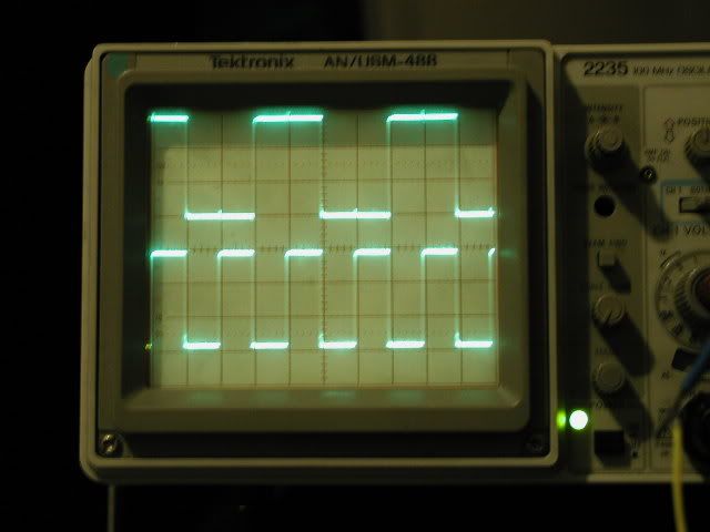
The below image shows the gates of the IRFZ44N fets before a 100 ohm resistor. So the green trace is the signal that is fed to the 5 fets that don't get hot real fast. The yellow trace is the signal that is fed to the 5 fets that get hot fast.
...SMPS...? You mean the chip for the PWM supply? That's the TL494 right? Ok, I get basically a flat line at 12v on the outputs (pin 8 and 11) of the TL494. Bad chip? Bad driver transistors? I do however get a nice sawtooth wave on pin 5...
"with not amps connected" and "Are the amps disconnected?" What do you mean Brett? Do you mean no speakers connected? There aren't any connected.
"CRO"? What's that?
Caps are not leaking, nor are they swollen like you often see.
Can't test the diodes very good w/o taking them out of the board because of how they are wired: 3 dual diodes in parallel with common cathodes.
The below image shows the gates of the IRFZ44N fets before a 100 ohm resistor. So the green trace is the signal that is fed to the 5 fets that don't get hot real fast. The yellow trace is the signal that is fed to the 5 fets that get hot fast.
...SMPS...? You mean the chip for the PWM supply? That's the TL494 right? Ok, I get basically a flat line at 12v on the outputs (pin 8 and 11) of the TL494. Bad chip? Bad driver transistors? I do however get a nice sawtooth wave on pin 5...
Attachments
Hi
There must be something wrong in that area. Can you post pic of amp where this TL is and it's surrounding components are?
I think that you are getting shorts on primary, as one side does close (not great looking waveform), but still they probably do. Other side is always on. If pins 9 and 10 don't go low at anytime, then TL is dead. If they do, you probably do have buffer(two transistors that are driven by TL, and drive fets(irfz's)) after TL, it is possible that one of them is not working (the one connected to + input rail).
By now you know that there is too much current going to amp, so I hope you have some way of limiting it, you don't want do destroy another set of IRFZ's
"with not amps connected" and "Are the amps disconnected?"
By that they would disconnect amplifier on board from smps. If you can, not destroying PCB, do that, if not leave as it is.
If you have sawtooth on pin 5 this is ok, but output could be dead...
First thing you wan't to do is to get both sides of fets to close and open when other side is not. Hope you know what I mean here
There must be something wrong in that area. Can you post pic of amp where this TL is and it's surrounding components are?
I think that you are getting shorts on primary, as one side does close (not great looking waveform
), but still they probably do. Other side is always on. If pins 9 and 10 don't go low at anytime, then TL is dead. If they do, you probably do have buffer(two transistors that are driven by TL, and drive fets(irfz's)) after TL, it is possible that one of them is not working (the one connected to + input rail).By now you know that there is too much current going to amp, so I hope you have some way of limiting it, you don't want do destroy another set of IRFZ's
"with not amps connected" and "Are the amps disconnected?"
By that they would disconnect amplifier on board from smps. If you can, not destroying PCB, do that, if not leave as it is.
If you have sawtooth on pin 5 this is ok, but output could be dead...
First thing you wan't to do is to get both sides of fets to close and open when other side is not.
Hope you know what I mean here Nothing is visibly wrong... I will post the pics tonight.
Pins 9 and 10: Both Pulsing square waves in a similar fashion.
I have a box I built with 2 DPDT switches and Four 1ohm 50watt resistors in an old coleman inverter heatsink. It always uses all 4 resistors no matter how the switches are switched. Depending upon how I switch the switches, I get 1/2ohm, 2.5ohm, or 4 ohms. I've been using it to limit current, as I don't have a current limited supply.
To disconnect the amp section, I could easily remove the HIP4080. Would that work? If not, I could remove the rectifier diodes without too much trouble.
"Both sides of the fets to close and open when the other side is not": You mean that only 5 fets should be active at a time with no overlapping of the other 5. They will alternate.
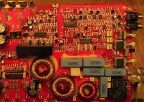
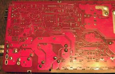
Here are the PICs. The TL494 is the one above the black rectangular thing. Haven't got a clue what that black thing is - no markings on it...
The pic of the bottom of the board is with it flipped horizontally, not vertically.
I can do much better closeups if need be, but it looked like you could see enough detail in these. Well, that and the fact that this website only lets you upload 100k byte images with a max of 1000x1000 pixels. Odd, I can't see any reason to limit BOTH size and resolution... Oh well.
Attachments
Hi
Left from TL there are 2 pairs of transistors, 2 pair od buffers that drive gates of fets. If TL drives this buffers ok, then check if this buffer drive gates of fets right. If they don't they may be damaged but there could be some other thing, like only one of fet is dead and it does appear like all of them are. Signal on fets should go from GND =0V to Vbat =~13v and back again with freq. at wich smps operates.
If you can't find any error from output of TL to gates of fets, you might consider removing all fets, check signals of buffers,... then put in two good fets, one on each side and work your way from there. I think that one transistor in buffer that drives side of fets that is on at all time, is damaged.
Gate waveform should look as close to this as you can bring it.
I don't really understand your image. What are the 2 scope leads on? The gates of the 2 sets of FETs?
Anyway, the attached image on this post is the output from Pin 9 (green trace) and Pin 10 (yellow trace) of the TL494.
A few posts above I posted the output from the buffer transistors. I am confident that all FETs are Ok, so think I'm going to replace all 4 buffer transistors.
The buffer transistors are KTC3198 and KTA1266. Compatible parts are 2sc3198 and 2sa1266 right? I'm thinking of using some Fairchild part subs like:
KSC1815 in place of the C3198
KSA1015 in place of the A1266
Opinions?
Attachments
- Status
- This old topic is closed. If you want to reopen this topic, contact a moderator using the "Report Post" button.
- Home
- Amplifiers
- Class D
- Fixing a BOSS REV3000D amp