Dual Mono 3886 kit ordered recently
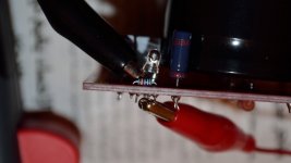
alright i think i installed the blue LED backwards.
the long leg against the ">" arrow
from what i understood of the guide:
"arrow ">" this points towards where the long leg is soldered in.
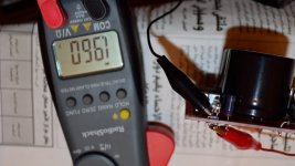
multimeter gives reading(1.960) only when reversing the testing leads and dont light up LED.
when i was soldering the LED lit up briefly lol
is this a problem? is there another way to test it?
thanks
alright i think i installed the blue LED backwards.
the long leg against the ">" arrow
from what i understood of the guide:
"arrow ">" this points towards where the long leg is soldered in.
multimeter gives reading(1.960) only when reversing the testing leads and dont light up LED.
when i was soldering the LED lit up briefly lol
is this a problem? is there another way to test it?
thanks
Attachments
A good way of testing LEDs is to use a lithium coin cell such as a 2016. I have dozens around here as I bought a batch of 50 keyring torches from dealextreme.com to use as doglights.
You can connect the LED momentarily directly across the coin cell. They have ~3.6V out which is sufficient to cause any LED to strike, but so little current drive capacity that destruction of the LED is unlikely unless it has a VERY low power rating, I've never blown one up doing this.
You can connect the LED momentarily directly across the coin cell. They have ~3.6V out which is sufficient to cause any LED to strike, but so little current drive capacity that destruction of the LED is unlikely unless it has a VERY low power rating, I've never blown one up doing this.
hey counter culture,
nice tricks!(they are avaliable everywhere)") i will try them for sure, but i'm more inclined to just cancel the led.
i will try them for sure, but i'm more inclined to just cancel the led.
can i install a jumper wire instead?
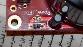
here you can see a picture of the led i removed just now
the long leg supposed to go on the left against the arrow?
nice tricks!(they are avaliable everywhere)
i will try them for sure, but i'm more inclined to just cancel the led.can i install a jumper wire instead?
here you can see a picture of the led i removed just now
the long leg supposed to go on the left against the arrow?
Attachments
If the LED is just purely cosmetic then you can just omit it with no further action.
You say the LED lit while soldering ? You soldered with it powered up or with the caps fully charged ? If the iron was earthed then you could have a low resistance path via the iron that zapped the LED.
You say the LED lit while soldering ? You soldered with it powered up or with the caps fully charged ? If the iron was earthed then you could have a low resistance path via the iron that zapped the LED.
the board is not in a condition to be powered up still
no the boards still not wired to ac.
i just saw briefly a blue flash reflected off the worktable
the iron is 2 wire so maybe its not earth? strangest thing... anyhow yeah i will check if it is cosmetic then i dont need this.
maybe the tip is somehow carrying voltage? (no idea about this making sense or no)
the board is not in a condition to be powered up still
no the boards still not wired to ac.
i just saw briefly a blue flash reflected off the worktable
the iron is 2 wire so maybe its not earth? strangest thing... anyhow yeah i will check if it is cosmetic then i dont need this.
maybe the tip is somehow carrying voltage? (no idea about this making sense or no)
Leakage from an iron can happen but it would need the PCB to have a return path somewhere. Might be worth measuring the AC voltage on the working iron to a known mains ground point. If you do read any voltage then I have a hazy recollection that the leakage current should be under 5 micro amps for a good iron.
- Status
- This old topic is closed. If you want to reopen this topic, contact a moderator using the "Report Post" button.
- Home
- More Vendors...
- Chipamp
- noob: blue LED polarity