
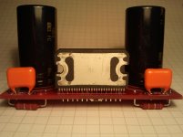
You'll need a 10k resistor, 1/4W will do fine. Look at the attached pic, it's at the top in the middle.
On the underside of the board there are two solder pads, a 1206 package size SMD resistor, or as in my case, a MELF resistor (MMA 0204 series) fits nicely. You could also use a regular resistor with it's leads bent accordingly.
Oh, and do yourself a favor and add coupling caps at the input. With 22k to ground it should be between 1.47uF and 2.2uF (-3dB @ 5Hz which is 2 octaves down from 20Hz).
Attachments
Last edited:
3R3 is perfectly fine. See http://www.diyaudio.com/forums/chip-amps/120028-boucherot-cell-zobel-network-values.html for a little more on that topic.
So, I have a question regarding the poly caps (Cz1, Cz2). I am a mechanical engineer, not an electrical/audio engineer, and I was wondering what the difference would be if I used metalized polypropylene caps instead of the "standard" polypropylene caps listed in the BOM? Here are pics of the two caps. The smaller one is the metalized polypropylene and the larger one (supplied in a different chipamp.com kit) is what I was hoping to get, but both Mouser and Digikey don't have the "standard" polypropylene caps at that voltage/capacitance, just the metalized ones.
Huh, seems imgur doesn't like to play nice here? What are the magic instructions to get pics to post here?
An externally hosted image should be here but it was not working when we last tested it.
Huh, seems imgur doesn't like to play nice here? What are the magic instructions to get pics to post here?
Last edited:
Regarding capacitor types...film caps basically come in two flavors: film-and-foil or metalized-foil. The former really has dedicated metal foils for the electrodes, and the dielectric is sandwiched between them. The latter type has metal deposited on the plastic foil (sputtered or so).
It seems to be generally accepted/believed that the metalized-foil types can be noisier due to the thinner (more grainy) and less uniform metal layer. There are also like a dozen different plastic foil types, all having a different permittivity.
To answer your question...at audio frequencies the Zobel network is inactive and should thus have no influence on the sound. Only at higher frequencies (couple hundred kHz) it kicks in and compensates the speaker's rising impedance so that the amp still has a load. Different film cap types will, in my opinion, not have a big influence on the Zobel network.
Okay finished it this morning and been having a listen; they sound great.
As some advice on the layout, as a tester speaking, I think the mute should be usable as in easy use of a switch. I think perhaps the resistor Rm should be hole through mounted and a jump should be an option which you can also hook a switch up to. The Rz resistors need to be printed on the board apart from that I think they are fantastic little boards.
Thanks for the opportunity to test.
Boscoe.
I am fairly new to the forum, and I am not sure if this is bad form, but I posted this to the LM3886 Beta Build thread as well, but I wanted to let others know about the board dimensions. I apologize if it is bad form. Someone please let me know if it is.
I saw that someone was wondering what the dimensions of one of the chipamp boards was, and while I can't help him with those dimensions, I can put the dimensions of the LM3886 Mono Board up here for people to see. I finally got it populated today and will spend the next few weeks (family, job, house and all) building the enclosure for them. Well, here is the link to the pics:
I also ordered and built the LM4780 Parallel board [LM4780 (1)] pics here:
And I ordered the LM4780 Bridge/Stereo board [LM4780 (2)] but have not put it together yet. Here are the pics of it as well:
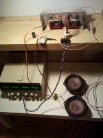
Since I was at it, I took pics of the ChipAmp power supply. I am using one per LM4780 parallel amp.
I needed something to do this winter I guess.
I saw that someone was wondering what the dimensions of one of the chipamp boards was, and while I can't help him with those dimensions, I can put the dimensions of the LM3886 Mono Board up here for people to see. I finally got it populated today and will spend the next few weeks (family, job, house and all) building the enclosure for them. Well, here is the link to the pics:
An externally hosted image should be here but it was not working when we last tested it.
I also ordered and built the LM4780 Parallel board [LM4780 (1)] pics here:
An externally hosted image should be here but it was not working when we last tested it.
And I ordered the LM4780 Bridge/Stereo board [LM4780 (2)] but have not put it together yet. Here are the pics of it as well:
An externally hosted image should be here but it was not working when we last tested it.
Since I was at it, I took pics of the ChipAmp power supply. I am using one per LM4780 parallel amp.
An externally hosted image should be here but it was not working when we last tested it.
I needed something to do this winter I guess.
Good stuff, hey if your still having problems with the picture uploads, (I can't see them)
Scroll down, you'll see a box that says "manage attachments", click that then browse to your file location and upload.
Now you'll likely have to resize your pics too (first), not sure what the limit is here but most digital cameras take a huge picture. (File Size) So, highlight your picture, right click on it...open with> Paint. Click "resize" , top left area, then check the "pixels" circle and enter a horizontal width. I enter 500 - 1000 depending on how big you want it to be. This makes life much easier uploading and a clickable "thumbnail" image should show up right in your post.
- Status
- This old topic is closed. If you want to reopen this topic, contact a moderator using the "Report Post" button.
- Home
- More Vendors...
- Chipamp
- Chipamp 4780 (1) Beta Build